

458
8 Morphogenesis
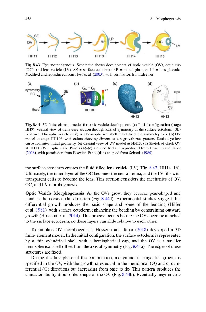
Fig. 8.43 Eye morphogenesis. Schematic shows development of optic vesicle (OV), optic cup
(OC), and lens vesicle (LV). SE = surface ectoderm; RP = retinal placode; LP = lens placode.
Modified and reproduced from Hyer et al. (2003), with permission from Elsevier
Fig. 8.44 3D finite-element model for optic vesicle development. (a) Initial configuration (stage
HH9). Ventral view of transverse section through axis of symmetry of the surface ectoderm (SE)
is shown. The optic vesicle (OV) is a hemispherical shell offset from the symmetry axis. (b) OV
model at stage HH10 + with colors showing dimensionless growth-rate pattern. Dashed yellow
curve indicates initial geometry. (c) Cranial view of OV model at HH13. (d) Sketch of chick OV
at HH13. OS = optic stalk. Panels (a)–(c) are modified and reproduced from Hosseini and Taber
(2018), with permission from Elsevier. Panel (d) is adapted from Schook (1980)
the surface ectoderm creates the fluid-filled lens vesicle (LV) (Fig. 8.43, HH14–16).
Ultimately, the inner layer of the OC becomes the neural retina, and the LV fills with
transparent cells to become the lens. This section considers the mechanics of OV,
OC, and LV morphogenesis.
Optic Vesicle Morphogenesis As the OVs grow, they become pear-shaped and
bend in the dorsocaudal direction (Fig. 8.44d). Experimental studies suggest that
differential growth produces the basic shape and some of the bending (Hilfer
et al. 1981), with surface ectoderm enhancing the bending by constraining outward
growth (Hosseini et al. 2014). This process occurs before the OVs become attached
to the surface ectoderm, so these layers can slide relative to each other.
To simulate OV morphogenesis, Hosseini and Taber (2018) developed a 3D
finite-element model. In the initial configuration, the surface ectoderm is represented
by a thin cylindrical shell with a hemispherical cap, and the OV is a smaller
hemispherical shell offset from the axis of symmetry (Fig. 8.44a). The edges of these
structures are fixed.
During the first phase of the computation, axisymmetric tangential growth is
specified in the OV, with the growth rates equal in the meridional () and circumferential () directions but increasing from base to tip. This pattern produces the
characteristic light-bulb-like shape of the OV (Fig. 8.44b). Eventually, asymmetric
8 Morphogenesis
Fig. 8.43 Eye morphogenesis. Schematic shows development of optic vesicle (OV), optic cup
(OC), and lens vesicle (LV). SE = surface ectoderm; RP = retinal placode; LP = lens placode.
Modified and reproduced from Hyer et al. (2003), with permission from Elsevier
Fig. 8.44 3D finite-element model for optic vesicle development. (a) Initial configuration (stage
HH9). Ventral view of transverse section through axis of symmetry of the surface ectoderm (SE)
is shown. The optic vesicle (OV) is a hemispherical shell offset from the symmetry axis. (b) OV
model at stage HH10 + with colors showing dimensionless growth-rate pattern. Dashed yellow
curve indicates initial geometry. (c) Cranial view of OV model at HH13. (d) Sketch of chick OV
at HH13. OS = optic stalk. Panels (a)–(c) are modified and reproduced from Hosseini and Taber
(2018), with permission from Elsevier. Panel (d) is adapted from Schook (1980)
the surface ectoderm creates the fluid-filled lens vesicle (LV) (Fig. 8.43, HH14–16).
Ultimately, the inner layer of the OC becomes the neural retina, and the LV fills with
transparent cells to become the lens. This section considers the mechanics of OV,
OC, and LV morphogenesis.
Optic Vesicle Morphogenesis As the OVs grow, they become pear-shaped and
bend in the dorsocaudal direction (Fig. 8.44d). Experimental studies suggest that
differential growth produces the basic shape and some of the bending (Hilfer
et al. 1981), with surface ectoderm enhancing the bending by constraining outward
growth (Hosseini et al. 2014). This process occurs before the OVs become attached
to the surface ectoderm, so these layers can slide relative to each other.
To simulate OV morphogenesis, Hosseini and Taber (2018) developed a 3D
finite-element model. In the initial configuration, the surface ectoderm is represented
by a thin cylindrical shell with a hemispherical cap, and the OV is a smaller
hemispherical shell offset from the axis of symmetry (Fig. 8.44a). The edges of these
structures are fixed.
During the first phase of the computation, axisymmetric tangential growth is
specified in the OV, with the growth rates equal in the meridional () and circumferential () directions but increasing from base to tip. This pattern produces the
characteristic light-bulb-like shape of the OV (Fig. 8.44b). Eventually, asymmetric