

276
6 Growth
(R,4,Z)
I
I
B
P
(U,-,])
B 0
(r,T,z)
P
p i
a
b
B L
F 1
F 2
F
a 0
b 0
>O R , O 4 , O Z ]
>O r , O T , O z ]
>O U , O - , O ] ]
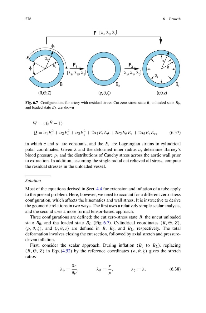
Fig. 6.7 Configurations for artery with residual stress. Cut zero-stress state B, unloaded state B 0 ,
and loaded state B L are shown
W = c(e
Q
− 1)
Q = α 1 E
2
r + α 2 E
2
θ + α 3 E
2
z + 2α 4 E r E θ + 2α 5 E θ E z + 2α 6 E z E r ,
(6.37)
in which c and α i are constants, and the E i are Lagrangian strains in cylindrical
polar coordinates. Given λ and the deformed inner radius a, determine Barney’s
blood pressure p i and the distributions of Cauchy stress across the aortic wall prior
to extraction. In addition, assuming the single radial cut relieved all stress, compute
the residual stresses in the unloaded vessel.
Solution
Most of the equations derived in Sect. 4.4 for extension and inflation of a tube apply
to the present problem. Here, however, we need to account for a different zero-stress
configuration, which affects the kinematics and wall stress. It is instructive to derive
the geometric relations in two ways. The first uses a relatively simple scalar analysis,
and the second uses a more formal tensor-based approach.
Three configurations are defined: the cut zero-stress state B, the uncut unloaded
state B 0 , and the loaded state B L (Fig. 6.7). Cylindrical coordinates (R, ,, Z),
(ρ, ϑ, ζ ), and (r, θ, z) are defined in B, B 0 , and B L , respectively. The total
deformation involves closing the cut section, followed by axial stretch and pressuredriven inflation.
First, consider the scalar approach. During inflation (B 0 to B L ), replacing
(R, ,, Z) in Eqs. (4.52) by the reference coordinates (ρ, ϑ, ζ ) gives the stretch
ratios
λ ρ =
∂r
∂ρ
,
λ ϑ =
r
ρ
,
λ ζ = λ.
(6.38)
6 Growth
(R,4,Z)
I
I
B
P
(U,-,])
B 0
(r,T,z)
P
p i
a
b
B L
F 1
F 2
F
a 0
b 0
>O R , O 4 , O Z ]
>O r , O T , O z ]
>O U , O - , O ] ]
Fig. 6.7 Configurations for artery with residual stress. Cut zero-stress state B, unloaded state B 0 ,
and loaded state B L are shown
W = c(e
Q
− 1)
Q = α 1 E
2
r + α 2 E
2
θ + α 3 E
2
z + 2α 4 E r E θ + 2α 5 E θ E z + 2α 6 E z E r ,
(6.37)
in which c and α i are constants, and the E i are Lagrangian strains in cylindrical
polar coordinates. Given λ and the deformed inner radius a, determine Barney’s
blood pressure p i and the distributions of Cauchy stress across the aortic wall prior
to extraction. In addition, assuming the single radial cut relieved all stress, compute
the residual stresses in the unloaded vessel.
Solution
Most of the equations derived in Sect. 4.4 for extension and inflation of a tube apply
to the present problem. Here, however, we need to account for a different zero-stress
configuration, which affects the kinematics and wall stress. It is instructive to derive
the geometric relations in two ways. The first uses a relatively simple scalar analysis,
and the second uses a more formal tensor-based approach.
Three configurations are defined: the cut zero-stress state B, the uncut unloaded
state B 0 , and the loaded state B L (Fig. 6.7). Cylindrical coordinates (R, ,, Z),
(ρ, ϑ, ζ ), and (r, θ, z) are defined in B, B 0 , and B L , respectively. The total
deformation involves closing the cut section, followed by axial stretch and pressuredriven inflation.
First, consider the scalar approach. During inflation (B 0 to B L ), replacing
(R, ,, Z) in Eqs. (4.52) by the reference coordinates (ρ, ϑ, ζ ) gives the stretch
ratios
λ ρ =
∂r
∂ρ
,
λ ϑ =
r
ρ
,
λ ζ = λ.
(6.38)