

410
P. Liu
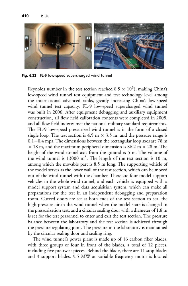
Fig. 6.32 FL-9 low-speed supercharged wind tunnel
Reynolds number in the test section reached 8.5 × 10 6 ), making China’s
low-speed wind tunnel test equipment and test technology level among
the international advanced ranks, greatly increasing China’s low-speed
wind tunnel test capacity. FL-9 low-speed supercharged wind tunnel
was built in 2006. After equipment debugging and auxiliary equipment
construction, all flow field calibration contents were completed in 2008,
and all flow field indexes met the national military standard requirements.
The FL-9 low-speed pressurized wind tunnel is in the form of a closed
single loop. The test section is 4.5 m × 3.5 m, and the pressure range is
0.1−0.4 mpa. The dimensions between the rectangular loop axes are 78 m
× 18 m, and the maximum peripheral dimension is 86.2 m × 28 m. The
height of the wind tunnel axis from the ground is 5 m. The volume of
the wind tunnel is 13000 m 3 . The length of the test section is 10 m,
among which the movable part is 8.5 m long. The supporting vehicle of
the model serves as the lower wall of the test section, which can be moved
out of the wind tunnel with the chamber. There are four model support
vehicles in the whole wind tunnel, and each vehicle is equipped with a
model support system and data acquisition system, which can make all
preparations for the test in an independent debugging and preparation
room. Curved doors are set at both ends of the test section to seal the
high-pressure air in the wind tunnel when the model state is changed in
the pressurization test, and a circular sealing door with a diameter of 1.8 m
is set for the test personnel to enter and exit the test section. The pressure
balance between the laboratory and the test section is achieved through
the pressure regulating joint. The pressure in the laboratory is maintained
by the circular sealing door and sealing ring.
The wind tunnel’s power plant is made up of 16 carbon fiber blades,
with three groups of four in front of the blades, a total of 12 pieces,
including five pre-twist pieces. Behind the blade, there are 11 stop blades
and 3 support blades. 9.5 MW ac variable frequency motor is located
P. Liu
Fig. 6.32 FL-9 low-speed supercharged wind tunnel
Reynolds number in the test section reached 8.5 × 10 6 ), making China’s
low-speed wind tunnel test equipment and test technology level among
the international advanced ranks, greatly increasing China’s low-speed
wind tunnel test capacity. FL-9 low-speed supercharged wind tunnel
was built in 2006. After equipment debugging and auxiliary equipment
construction, all flow field calibration contents were completed in 2008,
and all flow field indexes met the national military standard requirements.
The FL-9 low-speed pressurized wind tunnel is in the form of a closed
single loop. The test section is 4.5 m × 3.5 m, and the pressure range is
0.1−0.4 mpa. The dimensions between the rectangular loop axes are 78 m
× 18 m, and the maximum peripheral dimension is 86.2 m × 28 m. The
height of the wind tunnel axis from the ground is 5 m. The volume of
the wind tunnel is 13000 m 3 . The length of the test section is 10 m,
among which the movable part is 8.5 m long. The supporting vehicle of
the model serves as the lower wall of the test section, which can be moved
out of the wind tunnel with the chamber. There are four model support
vehicles in the whole wind tunnel, and each vehicle is equipped with a
model support system and data acquisition system, which can make all
preparations for the test in an independent debugging and preparation
room. Curved doors are set at both ends of the test section to seal the
high-pressure air in the wind tunnel when the model state is changed in
the pressurization test, and a circular sealing door with a diameter of 1.8 m
is set for the test personnel to enter and exit the test section. The pressure
balance between the laboratory and the test section is achieved through
the pressure regulating joint. The pressure in the laboratory is maintained
by the circular sealing door and sealing ring.
The wind tunnel’s power plant is made up of 16 carbon fiber blades,
with three groups of four in front of the blades, a total of 12 pieces,
including five pre-twist pieces. Behind the blade, there are 11 stop blades
and 3 support blades. 9.5 MW ac variable frequency motor is located