

196
P. Liu
where z is the height difference between the water level of the water tower
and the water level of the water storage well. h w1-4 is the head loss of liquid
flow from the water storage well to section 4-4 of the water tower. H P is the
head of the water pump, which represents the mechanical energy absorbed by
the liquid per unit time and weight, also known as the total head of the water
pump. For total discharge Q, the total mechanical power obtained from the
pump is
N P =
γ Q H P
η
where η is the total efficiency of the water pump.
3.4.3 Water Turbine System
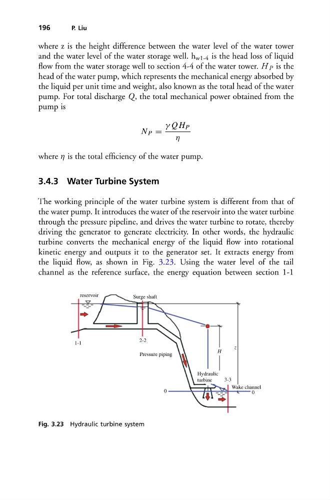
The working principle of the water turbine system is different from that of
the water pump. It introduces the water of the reservoir into the water turbine
through the pressure pipeline, and drives the water turbine to rotate, thereby
driving the generator to generate electricity. In other words, the hydraulic
turbine converts the mechanical energy of the liquid flow into rotational
kinetic energy and outputs it to the generator set. It extracts energy from
the liquid flow, as shown in Fig. 3.23. Using the water level of the tail
channel as the reference surface, the energy equation between section 1-1
reservoir
Surge shaft
Pressure piping
Hydraulic
turbine
3-3
Wake channel
0
0
H
z
1-1
2-2
Fig. 3.23 Hydraulic turbine system
P. Liu
where z is the height difference between the water level of the water tower
and the water level of the water storage well. h w1-4 is the head loss of liquid
flow from the water storage well to section 4-4 of the water tower. H P is the
head of the water pump, which represents the mechanical energy absorbed by
the liquid per unit time and weight, also known as the total head of the water
pump. For total discharge Q, the total mechanical power obtained from the
pump is
N P =
γ Q H P
η
where η is the total efficiency of the water pump.
3.4.3 Water Turbine System
The working principle of the water turbine system is different from that of
the water pump. It introduces the water of the reservoir into the water turbine
through the pressure pipeline, and drives the water turbine to rotate, thereby
driving the generator to generate electricity. In other words, the hydraulic
turbine converts the mechanical energy of the liquid flow into rotational
kinetic energy and outputs it to the generator set. It extracts energy from
the liquid flow, as shown in Fig. 3.23. Using the water level of the tail
channel as the reference surface, the energy equation between section 1-1
reservoir
Surge shaft
Pressure piping
Hydraulic
turbine
3-3
Wake channel
0
0
H
z
1-1
2-2
Fig. 3.23 Hydraulic turbine system