

amount of organics products in the permeate increases as well (Tomaszewska et al.
1998; Molinari et al. 2004; Mozia et al. 2006), and the pressure to be applied
decreases.
Most of the photocatalytic membrane reactors studied in the literature combine
photocatalysis with membrane process, involving microfiltration (Erdei et al. 2008;
Shon et al. 2008; Benotti et al. 2009), ultrafiltration (Sun et al. 2004; Fu et al. 2006a,
b; Tsarenko et al. 2006), and nanofiltration (Augugliaro et al. 2005; Molinari et al.
2006: Molinari et al. 2008
In order to overcome the fouling phenomenon, new types of PMRs combining
membrane reactors with direct contact membrane distillation (Mozia et al. 2008;
Mozia et al. 2009a, b), pervaporation (Camera-Roda and Santarelli 2005), and
dialysis (Azrague et al. 2007) were developed more recently.
Photocatalytic Membranes
TiO 2 Immobilized on/in the Membrane
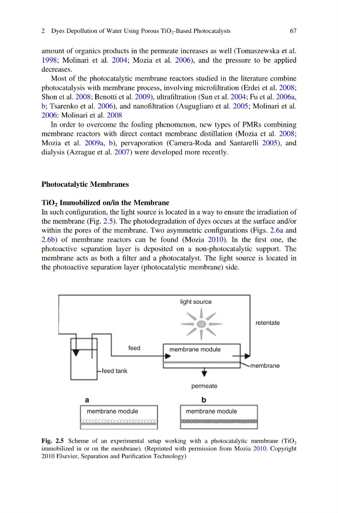
In such configuration, the light source is located in a way to ensure the irradiation of
the membrane (Fig. 2.5). The photodegradation of dyes occurs at the surface and/or
within the pores of the membrane. Two asymmetric configurations (Figs. 2.6a and
2.6b) of membrane reactors can be found (Mozia 2010). In the first one, the
photoactive separation layer is deposited on a non-photocatalytic support. The
membrane acts as both a filter and a photocatalyst. The light source is located in
the photoactive separation layer (photocatalytic membrane) side.
retentate
membrane
permeate
b
a
feed tank
feed
membrane module
light source
membrane module
membrane module
Fig. 2.5 Scheme of an experimental setup working with a photocatalytic membrane (TiO 2
immobilized in or on the membrane). (Reprinted with permission from Mozia 2010. Copyright
2010 Elsevier, Separation and Purification Technology)
2 Dyes Depollution of Water Using Porous TiO 2 -Based Photocatalysts
67
1998; Molinari et al. 2004; Mozia et al. 2006), and the pressure to be applied
decreases.
Most of the photocatalytic membrane reactors studied in the literature combine
photocatalysis with membrane process, involving microfiltration (Erdei et al. 2008;
Shon et al. 2008; Benotti et al. 2009), ultrafiltration (Sun et al. 2004; Fu et al. 2006a,
b; Tsarenko et al. 2006), and nanofiltration (Augugliaro et al. 2005; Molinari et al.
2006: Molinari et al. 2008
In order to overcome the fouling phenomenon, new types of PMRs combining
membrane reactors with direct contact membrane distillation (Mozia et al. 2008;
Mozia et al. 2009a, b), pervaporation (Camera-Roda and Santarelli 2005), and
dialysis (Azrague et al. 2007) were developed more recently.
Photocatalytic Membranes
TiO 2 Immobilized on/in the Membrane
In such configuration, the light source is located in a way to ensure the irradiation of
the membrane (Fig. 2.5). The photodegradation of dyes occurs at the surface and/or
within the pores of the membrane. Two asymmetric configurations (Figs. 2.6a and
2.6b) of membrane reactors can be found (Mozia 2010). In the first one, the
photoactive separation layer is deposited on a non-photocatalytic support. The
membrane acts as both a filter and a photocatalyst. The light source is located in
the photoactive separation layer (photocatalytic membrane) side.
retentate
membrane
permeate
b
a
feed tank
feed
membrane module
light source
membrane module
membrane module
Fig. 2.5 Scheme of an experimental setup working with a photocatalytic membrane (TiO 2
immobilized in or on the membrane). (Reprinted with permission from Mozia 2010. Copyright
2010 Elsevier, Separation and Purification Technology)
2 Dyes Depollution of Water Using Porous TiO 2 -Based Photocatalysts
67