

7. The segmentation results can be used to quantify the cellular
and molecular dynamics of cell movement during wound
repair, for instance by measuring the area of the wound over
time (Fig. 4b), the rate of wound closure (Fig. 4c, see Note 27),
or fluorescence dynamics at the leading edge of the advancing
cells (Fig. 4d, see Notes 28 and 29).
3.4.3 Super-Resolution
Radial Fluctuation
Microscopy of Living
Embryos
For image acquisition:
1. Prepare embryos as indicated in Subheading 3.4.1.
2. Initialize Micromanager 1.4, nightly build November 20, 2018
or later.
3. Select camera configuration and illumination settings in the
“Configuration Settings” panel in the top right corner of the
main Micromanager window. We recommend having a SRRFspecific “Group” or “Preset” to ensure that the appropriate
camera and illumination settings are used consistently.
4. Check that the camera parameters in the “Device Property
Browser” (“Tools > Device Property Browser”) are set to
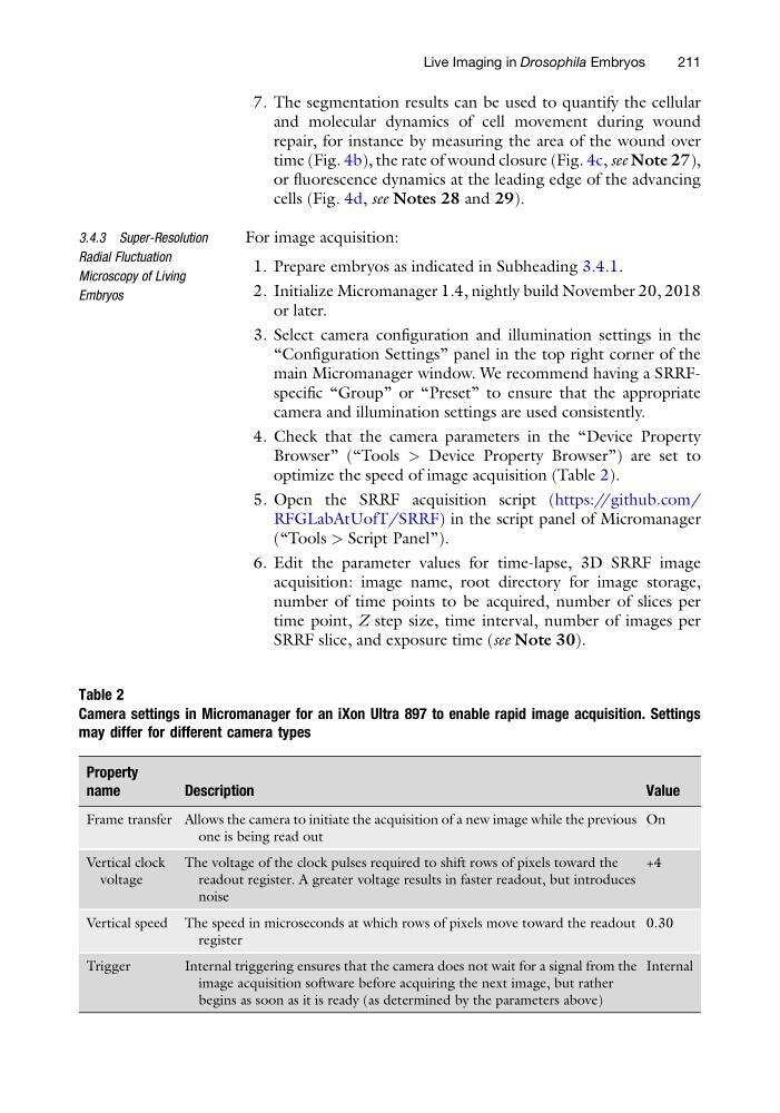
optimize the speed of image acquisition (Table 2).
5. Open the SRRF acquisition script (https://github.com/
RFGLabAtUofT/SRRF) in the script panel of Micromanager
(“Tools > Script Panel”).
6. Edit the parameter values for time-lapse, 3D SRRF image
acquisition: image name, root directory for image storage,
number of time points to be acquired, number of slices per
time point, Z step size, time interval, number of images per
SRRF slice, and exposure time (see Note 30).
Table 2
Camera settings in Micromanager for an iXon Ultra 897 to enable rapid image acquisition. Settings
may differ for different camera types
Property
name
Description
Value
Frame transfer Allows the camera to initiate the acquisition of a new image while the previous
one is being read out
On
Vertical clock
voltage
The voltage of the clock pulses required to shift rows of pixels toward the
readout register. A greater voltage results in faster readout, but introduces
noise
+4
Vertical speed The speed in microseconds at which rows of pixels move toward the readout
register
0.30
Trigger
Internal triggering ensures that the camera does not wait for a signal from the
image acquisition software before acquiring the next image, but rather
begins as soon as it is ready (as determined by the parameters above)
Internal
Live Imaging in Drosophila Embryos
211
and molecular dynamics of cell movement during wound
repair, for instance by measuring the area of the wound over
time (Fig. 4b), the rate of wound closure (Fig. 4c, see Note 27),
or fluorescence dynamics at the leading edge of the advancing
cells (Fig. 4d, see Notes 28 and 29).
3.4.3 Super-Resolution
Radial Fluctuation
Microscopy of Living
Embryos
For image acquisition:
1. Prepare embryos as indicated in Subheading 3.4.1.
2. Initialize Micromanager 1.4, nightly build November 20, 2018
or later.
3. Select camera configuration and illumination settings in the
“Configuration Settings” panel in the top right corner of the
main Micromanager window. We recommend having a SRRFspecific “Group” or “Preset” to ensure that the appropriate
camera and illumination settings are used consistently.
4. Check that the camera parameters in the “Device Property
Browser” (“Tools > Device Property Browser”) are set to
optimize the speed of image acquisition (Table 2).
5. Open the SRRF acquisition script (https://github.com/
RFGLabAtUofT/SRRF) in the script panel of Micromanager
(“Tools > Script Panel”).
6. Edit the parameter values for time-lapse, 3D SRRF image
acquisition: image name, root directory for image storage,
number of time points to be acquired, number of slices per
time point, Z step size, time interval, number of images per
SRRF slice, and exposure time (see Note 30).
Table 2
Camera settings in Micromanager for an iXon Ultra 897 to enable rapid image acquisition. Settings
may differ for different camera types
Property
name
Description
Value
Frame transfer Allows the camera to initiate the acquisition of a new image while the previous
one is being read out
On
Vertical clock
voltage
The voltage of the clock pulses required to shift rows of pixels toward the
readout register. A greater voltage results in faster readout, but introduces
noise
+4
Vertical speed The speed in microseconds at which rows of pixels move toward the readout
register
0.30
Trigger
Internal triggering ensures that the camera does not wait for a signal from the
image acquisition software before acquiring the next image, but rather
begins as soon as it is ready (as determined by the parameters above)
Internal
Live Imaging in Drosophila Embryos
211