

52
S. Conrad et al.
silicone tube connector for the test bench was located at one of the short sides. The tests
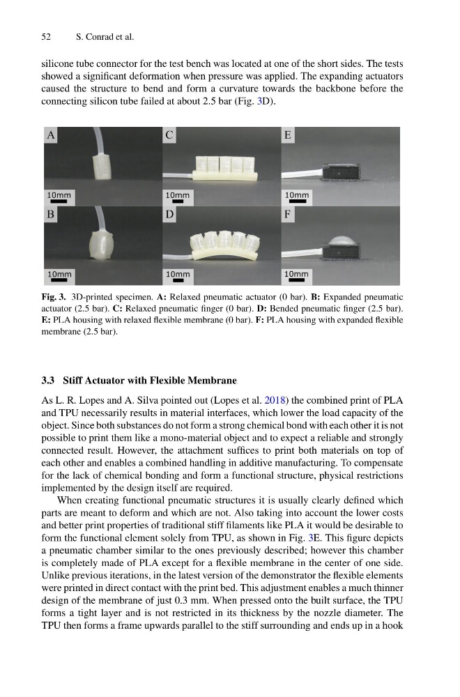
showed a significant deformation when pressure was applied. The expanding actuators
caused the structure to bend and form a curvature towards the backbone before the
connecting silicon tube failed at about 2.5 bar (Fig. 3D).
Fig. 3. 3D-printed specimen. A: Relaxed pneumatic actuator (0 bar). B: Expanded pneumatic
actuator (2.5 bar). C: Relaxed pneumatic finger (0 bar). D: Bended pneumatic finger (2.5 bar).
E: PLA housing with relaxed flexible membrane (0 bar). F: PLA housing with expanded flexible
membrane (2.5 bar).
3.3 Stiff Actuator with Flexible Membrane
As L. R. Lopes and A. Silva pointed out (Lopes et al. 2018) the combined print of PLA
and TPU necessarily results in material interfaces, which lower the load capacity of the
object. Since both substances do not form a strong chemical bond with each other it is not
possible to print them like a mono-material object and to expect a reliable and strongly
connected result. However, the attachment suffices to print both materials on top of
each other and enables a combined handling in additive manufacturing. To compensate
for the lack of chemical bonding and form a functional structure, physical restrictions
implemented by the design itself are required.
When creating functional pneumatic structures it is usually clearly defined which
parts are meant to deform and which are not. Also taking into account the lower costs
and better print properties of traditional stiff filaments like PLA it would be desirable to
form the functional element solely from TPU, as shown in Fig. 3E. This figure depicts
a pneumatic chamber similar to the ones previously described; however this chamber
is completely made of PLA except for a flexible membrane in the center of one side.
Unlike previous iterations, in the latest version of the demonstrator the flexible elements
were printed in direct contact with the print bed. This adjustment enables a much thinner
design of the membrane of just 0.3 mm. When pressed onto the built surface, the TPU
forms a tight layer and is not restricted in its thickness by the nozzle diameter. The
TPU then forms a frame upwards parallel to the stiff surrounding and ends up in a hook
S. Conrad et al.
silicone tube connector for the test bench was located at one of the short sides. The tests
showed a significant deformation when pressure was applied. The expanding actuators
caused the structure to bend and form a curvature towards the backbone before the
connecting silicon tube failed at about 2.5 bar (Fig. 3D).
Fig. 3. 3D-printed specimen. A: Relaxed pneumatic actuator (0 bar). B: Expanded pneumatic
actuator (2.5 bar). C: Relaxed pneumatic finger (0 bar). D: Bended pneumatic finger (2.5 bar).
E: PLA housing with relaxed flexible membrane (0 bar). F: PLA housing with expanded flexible
membrane (2.5 bar).
3.3 Stiff Actuator with Flexible Membrane
As L. R. Lopes and A. Silva pointed out (Lopes et al. 2018) the combined print of PLA
and TPU necessarily results in material interfaces, which lower the load capacity of the
object. Since both substances do not form a strong chemical bond with each other it is not
possible to print them like a mono-material object and to expect a reliable and strongly
connected result. However, the attachment suffices to print both materials on top of
each other and enables a combined handling in additive manufacturing. To compensate
for the lack of chemical bonding and form a functional structure, physical restrictions
implemented by the design itself are required.
When creating functional pneumatic structures it is usually clearly defined which
parts are meant to deform and which are not. Also taking into account the lower costs
and better print properties of traditional stiff filaments like PLA it would be desirable to
form the functional element solely from TPU, as shown in Fig. 3E. This figure depicts
a pneumatic chamber similar to the ones previously described; however this chamber
is completely made of PLA except for a flexible membrane in the center of one side.
Unlike previous iterations, in the latest version of the demonstrator the flexible elements
were printed in direct contact with the print bed. This adjustment enables a much thinner
design of the membrane of just 0.3 mm. When pressed onto the built surface, the TPU
forms a tight layer and is not restricted in its thickness by the nozzle diameter. The
TPU then forms a frame upwards parallel to the stiff surrounding and ends up in a hook