

38
T. Cheng et al.
A
B
C
D
E
X
Y
X
Y
X
Y
X
Y
X
Y
Z
EXPERIMENTAL RESULTS
FUNCTIONAL PARAMETERS
X
Y
Z
X
15 N
15 N
2 cm
1 N
1 N
1 N
F
G
H
I
J
X
Y
Z
X
Y
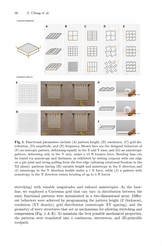
Fig. 1. Functional parameters include (A) pattern height, (B) resolution, (C) grid distribution, (D) amplitude, and (E) frequency. Shown here are the designed behaviors of
(F) an isotropic pattern, deforming equally in the X and Y axes, and (G) an anisotropic
pattern, deforming only in the Y axis, under a 15 N tension force. Bending bias can
be tuned via anisotropy and thickness, as exhibited by testing coupons with one edge
on a pin joint and string pulling from the free edge (allowing rotational freedom in the
XZ plane): patterns having (H) variable height and anisotropy in the Y direction and
(I) anisotropy in the Y direction buckle under a 1 N force, while (J) a pattern with
anisotropy in the X direction resists bending of up to 5 N forces.
stretching) with tunable magnitudes and tailored anisotropies. As the baseline, we employed a Cartesian grid that can vary in distribution between the
axes; functional patterns were instantiated in a two-dimensional array. Different behaviors were achieved by programming the pattern height (Z thickness),
resolution (XY density), grid distribution (anisotropic XY spacing), and the
geometry of wavy structures that act as mechanisms for allowing stretching and
compression (Fig. 1 A–E). To maintain the best possible mechanical properties,
the patterns were translated into a continuous, interwoven, and 3D-printable
toolpath.
T. Cheng et al.
A
B
C
D
E
X
Y
X
Y
X
Y
X
Y
X
Y
Z
EXPERIMENTAL RESULTS
FUNCTIONAL PARAMETERS
X
Y
Z
X
15 N
15 N
2 cm
1 N
1 N
1 N
F
G
H
I
J
X
Y
Z
X
Y
Fig. 1. Functional parameters include (A) pattern height, (B) resolution, (C) grid distribution, (D) amplitude, and (E) frequency. Shown here are the designed behaviors of
(F) an isotropic pattern, deforming equally in the X and Y axes, and (G) an anisotropic
pattern, deforming only in the Y axis, under a 15 N tension force. Bending bias can
be tuned via anisotropy and thickness, as exhibited by testing coupons with one edge
on a pin joint and string pulling from the free edge (allowing rotational freedom in the
XZ plane): patterns having (H) variable height and anisotropy in the Y direction and
(I) anisotropy in the Y direction buckle under a 1 N force, while (J) a pattern with
anisotropy in the X direction resists bending of up to 5 N forces.
stretching) with tunable magnitudes and tailored anisotropies. As the baseline, we employed a Cartesian grid that can vary in distribution between the
axes; functional patterns were instantiated in a two-dimensional array. Different behaviors were achieved by programming the pattern height (Z thickness),
resolution (XY density), grid distribution (anisotropic XY spacing), and the
geometry of wavy structures that act as mechanisms for allowing stretching and
compression (Fig. 1 A–E). To maintain the best possible mechanical properties,
the patterns were translated into a continuous, interwoven, and 3D-printable
toolpath.