

370
S. C. van den Berg et al.
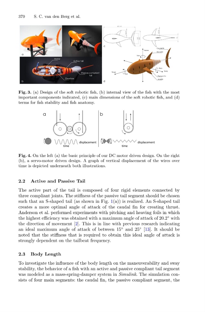
Fig. 3. (a) Design of the soft robotic fish, (b) internal view of the fish with the most
important components indicated, (c) main dimensions of the soft robotic fish, and (d)
terms for fish stability and fish anatomy.
Fig. 4. On the left (a) the basic principle of our DC motor driven design. On the right
(b), a servo-motor driven design. A graph of vertical displacement of the wires over
time is depicted underneath both illustrations.
2.2 Active and Passive Tail
The active part of the tail is composed of four rigid elements connected by
three compliant joints. The stiffness of the passive tail segment should be chosen
such that an S-shaped tail (as shown in Fig. 1(a)) is realized. An S-shaped tail
creates a more optimal angle of attack of the caudal fin for creating thrust.
Anderson et al. performed experiments with pitching and heaving foils in which
the highest efficiency was obtained with a maximum angle of attack of 20.2
◦ with
the direction of movement [2]. This is in line with previous research indicating
an ideal maximum angle of attack of between 15
◦ and 25
◦ [13]. It should be
noted that the stiffness that is required to obtain this ideal angle of attack is
strongly dependent on the tailbeat frequency.
2.3 Body Length
To investigate the influence of the body length on the maneuverability and sway
stability, the behavior of a fish with an active and passive compliant tail segment
was modeled as a mass-spring-damper system in Simulink. The simulation consists of four main segments: the caudal fin, the passive compliant segment, the
S. C. van den Berg et al.
Fig. 3. (a) Design of the soft robotic fish, (b) internal view of the fish with the most
important components indicated, (c) main dimensions of the soft robotic fish, and (d)
terms for fish stability and fish anatomy.
Fig. 4. On the left (a) the basic principle of our DC motor driven design. On the right
(b), a servo-motor driven design. A graph of vertical displacement of the wires over
time is depicted underneath both illustrations.
2.2 Active and Passive Tail
The active part of the tail is composed of four rigid elements connected by
three compliant joints. The stiffness of the passive tail segment should be chosen
such that an S-shaped tail (as shown in Fig. 1(a)) is realized. An S-shaped tail
creates a more optimal angle of attack of the caudal fin for creating thrust.
Anderson et al. performed experiments with pitching and heaving foils in which
the highest efficiency was obtained with a maximum angle of attack of 20.2
◦ with
the direction of movement [2]. This is in line with previous research indicating
an ideal maximum angle of attack of between 15
◦ and 25
◦ [13]. It should be
noted that the stiffness that is required to obtain this ideal angle of attack is
strongly dependent on the tailbeat frequency.
2.3 Body Length
To investigate the influence of the body length on the maneuverability and sway
stability, the behavior of a fish with an active and passive compliant tail segment
was modeled as a mass-spring-damper system in Simulink. The simulation consists of four main segments: the caudal fin, the passive compliant segment, the