

2 Interferometric Scattering (iSCAT) Microscopy and Related Techniques
33
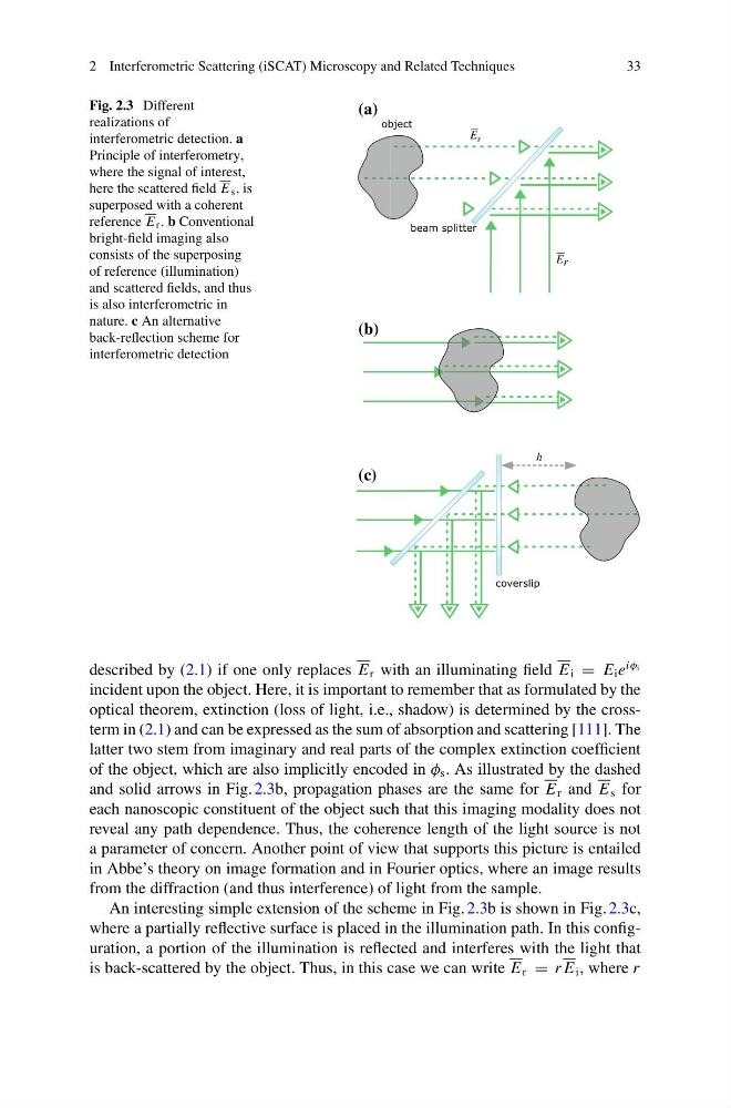
Fig. 2.3 Different
realizations of
interferometric detection. a
Principle of interferometry,
where the signal of interest,
here the scattered field E s , is
superposed with a coherent
reference E r . b Conventional
bright-field imaging also
consists of the superposing
of reference (illumination)
and scattered fields, and thus
is also interferometric in
nature. c An alternative
back-reflection scheme for
interferometric detection
coverslip
E r
E s
h
object
beam splitter
(a)
(b)
(c)
described by (2.1) if one only replaces E r with an illuminating field E i = E i e
iφ i
incident upon the object. Here, it is important to remember that as formulated by the
optical theorem, extinction (loss of light, i.e., shadow) is determined by the crossterm in (2.1) and can be expressed as the sum of absorption and scattering [111]. The
latter two stem from imaginary and real parts of the complex extinction coefficient
of the object, which are also implicitly encoded in φ s . As illustrated by the dashed
and solid arrows in Fig. 2.3b, propagation phases are the same for E r and E s for
each nanoscopic constituent of the object such that this imaging modality does not
reveal any path dependence. Thus, the coherence length of the light source is not
a parameter of concern. Another point of view that supports this picture is entailed
in Abbe’s theory on image formation and in Fourier optics, where an image results
from the diffraction (and thus interference) of light from the sample.
An interesting simple extension of the scheme in Fig. 2.3b is shown in Fig. 2.3c,
where a partially reflective surface is placed in the illumination path. In this configuration, a portion of the illumination is reflected and interferes with the light that
is back-scattered by the object. Thus, in this case we can write E r = r E i , where r
33
Fig. 2.3 Different
realizations of
interferometric detection. a
Principle of interferometry,
where the signal of interest,
here the scattered field E s , is
superposed with a coherent
reference E r . b Conventional
bright-field imaging also
consists of the superposing
of reference (illumination)
and scattered fields, and thus
is also interferometric in
nature. c An alternative
back-reflection scheme for
interferometric detection
coverslip
E r
E s
h
object
beam splitter
(a)
(b)
(c)
described by (2.1) if one only replaces E r with an illuminating field E i = E i e
iφ i
incident upon the object. Here, it is important to remember that as formulated by the
optical theorem, extinction (loss of light, i.e., shadow) is determined by the crossterm in (2.1) and can be expressed as the sum of absorption and scattering [111]. The
latter two stem from imaginary and real parts of the complex extinction coefficient
of the object, which are also implicitly encoded in φ s . As illustrated by the dashed
and solid arrows in Fig. 2.3b, propagation phases are the same for E r and E s for
each nanoscopic constituent of the object such that this imaging modality does not
reveal any path dependence. Thus, the coherence length of the light source is not
a parameter of concern. Another point of view that supports this picture is entailed
in Abbe’s theory on image formation and in Fourier optics, where an image results
from the diffraction (and thus interference) of light from the sample.
An interesting simple extension of the scheme in Fig. 2.3b is shown in Fig. 2.3c,
where a partially reflective surface is placed in the illumination path. In this configuration, a portion of the illumination is reflected and interferes with the light that
is back-scattered by the object. Thus, in this case we can write E r = r E i , where r