

338
I. I. Smolyaninov and V. N. Smolyaninova
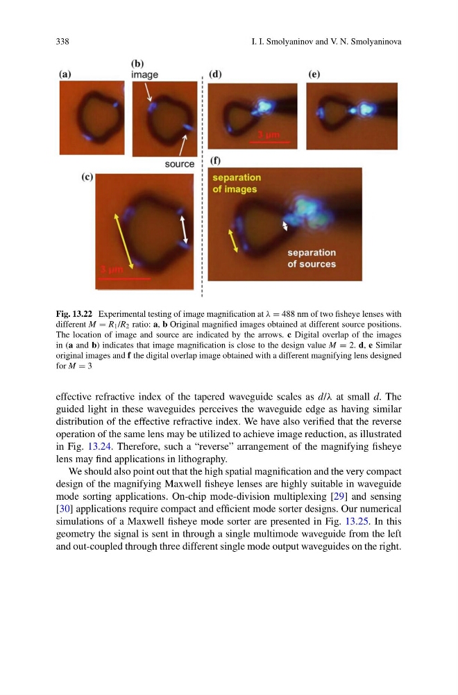
Fig. 13.22 Experimental testing of image magnification at λ = 488 nm of two fisheye lenses with
different M = R 1 /R 2 ratio: a, b Original magnified images obtained at different source positions.
The location of image and source are indicated by the arrows. c Digital overlap of the images
in (a and b) indicates that image magnification is close to the design value M = 2. d, e Similar
original images and f the digital overlap image obtained with a different magnifying lens designed
for M = 3
effective refractive index of the tapered waveguide scales as d/λ at small d. The
guided light in these waveguides perceives the waveguide edge as having similar
distribution of the effective refractive index. We have also verified that the reverse
operation of the same lens may be utilized to achieve image reduction, as illustrated
in Fig. 13.24. Therefore, such a “reverse” arrangement of the magnifying fisheye
lens may find applications in lithography.
We should also point out that the high spatial magnification and the very compact
design of the magnifying Maxwell fisheye lenses are highly suitable in waveguide
mode sorting applications. On-chip mode-division multiplexing [29] and sensing
[30] applications require compact and efficient mode sorter designs. Our numerical
simulations of a Maxwell fisheye mode sorter are presented in Fig. 13.25. In this
geometry the signal is sent in through a single multimode waveguide from the left
and out-coupled through three different single mode output waveguides on the right.
I. I. Smolyaninov and V. N. Smolyaninova
Fig. 13.22 Experimental testing of image magnification at λ = 488 nm of two fisheye lenses with
different M = R 1 /R 2 ratio: a, b Original magnified images obtained at different source positions.
The location of image and source are indicated by the arrows. c Digital overlap of the images
in (a and b) indicates that image magnification is close to the design value M = 2. d, e Similar
original images and f the digital overlap image obtained with a different magnifying lens designed
for M = 3
effective refractive index of the tapered waveguide scales as d/λ at small d. The
guided light in these waveguides perceives the waveguide edge as having similar
distribution of the effective refractive index. We have also verified that the reverse
operation of the same lens may be utilized to achieve image reduction, as illustrated
in Fig. 13.24. Therefore, such a “reverse” arrangement of the magnifying fisheye
lens may find applications in lithography.
We should also point out that the high spatial magnification and the very compact
design of the magnifying Maxwell fisheye lenses are highly suitable in waveguide
mode sorting applications. On-chip mode-division multiplexing [29] and sensing
[30] applications require compact and efficient mode sorter designs. Our numerical
simulations of a Maxwell fisheye mode sorter are presented in Fig. 13.25. In this
geometry the signal is sent in through a single multimode waveguide from the left
and out-coupled through three different single mode output waveguides on the right.