

176
P. Bianchini et al.
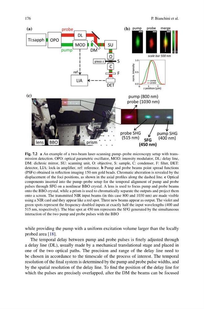
Fig. 7.2 a An example of a two-beam laser-scanning pump–probe microscopy setup with transmission detection. OPO: optical parametric oscillator, MOD: intensity modulator, DL: delay line,
DM: dichroic mirror, SU: scanning unit, O: objective, S: sample, C: condenser, F: filter, DET:
detector, LIA: lock-in amplifier, ref: reference. b Pump and probe beams point spread functions
(PSFs) obtained in reflection imaging 150-nm gold beads. Chromatic aberration is revealed by the
displacement of the foci positions, as shown in the axial profiles along the dashed line. c Optical
components inserted into the pump–probe setup for the temporal alignment of pump and probe
pulses through SFG on a nonlinear BBO crystal. A lens is used to focus pump and probe beams
onto the BBO crystal, while a prism is used to chromatically separate the outputs and project them
onto a screen. The transmitted NIR input beams (in this case 800 and 1030 nm) are made visible
using a NIR card and they appear like a red spot. Three new beams appear as output. The violet and
green spots represent the frequency-doubled inputs at exactly half the input wavelengths (400 and
515 nm, respectively). The blue spot at 450 nm represents the SFG generated by the simultaneous
interaction of the two pump and probe pulses with the BBO
while providing the pump with a uniform excitation volume larger than the locally
probed area [18].
The temporal delay between pump and probe pulses is finely adjusted through
a delay line (DL), usually made by a mechanical translational stage and placed in
one of the two optical paths. The precision and range of the delay line need to
be chosen in accordance to the timescale of the process of interest. The temporal
resolution of the final system is determined by the pump and probe pulse widths, and
by the spatial resolution of the delay line. To find the position of the delay line for
which the pulses are precisely overlapped, after the DM the beams can be focused
P. Bianchini et al.
Fig. 7.2 a An example of a two-beam laser-scanning pump–probe microscopy setup with transmission detection. OPO: optical parametric oscillator, MOD: intensity modulator, DL: delay line,
DM: dichroic mirror, SU: scanning unit, O: objective, S: sample, C: condenser, F: filter, DET:
detector, LIA: lock-in amplifier, ref: reference. b Pump and probe beams point spread functions
(PSFs) obtained in reflection imaging 150-nm gold beads. Chromatic aberration is revealed by the
displacement of the foci positions, as shown in the axial profiles along the dashed line. c Optical
components inserted into the pump–probe setup for the temporal alignment of pump and probe
pulses through SFG on a nonlinear BBO crystal. A lens is used to focus pump and probe beams
onto the BBO crystal, while a prism is used to chromatically separate the outputs and project them
onto a screen. The transmitted NIR input beams (in this case 800 and 1030 nm) are made visible
using a NIR card and they appear like a red spot. Three new beams appear as output. The violet and
green spots represent the frequency-doubled inputs at exactly half the input wavelengths (400 and
515 nm, respectively). The blue spot at 450 nm represents the SFG generated by the simultaneous
interaction of the two pump and probe pulses with the BBO
while providing the pump with a uniform excitation volume larger than the locally
probed area [18].
The temporal delay between pump and probe pulses is finely adjusted through
a delay line (DL), usually made by a mechanical translational stage and placed in
one of the two optical paths. The precision and range of the delay line need to
be chosen in accordance to the timescale of the process of interest. The temporal
resolution of the final system is determined by the pump and probe pulse widths, and
by the spatial resolution of the delay line. To find the position of the delay line for
which the pulses are precisely overlapped, after the DM the beams can be focused