

11 Meshless Algorithms for Computational Biomechanics of the Brain
285
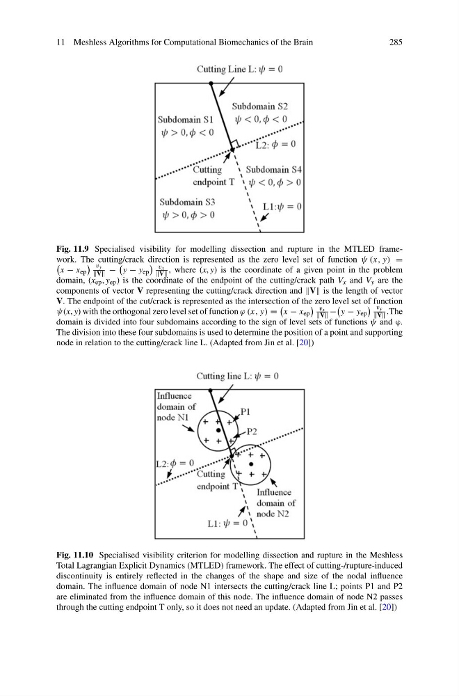
Fig. 11.9 Specialised visibility for modelling dissection and rupture in the MTLED framework. The cutting/crack direction is represented as the zero level set of function ψ (x, y) =
x − x ep
vy
V −
y − y ep
vx
V , where (x, y) is the coordinate of a given point in the problem
domain, (x ep , y ep ) is the coordinate of the endpoint of the cutting/crack path V x and V y are the
components of vector V representing the cutting/crack direction and is the length of vector
V. The endpoint of the cut/crack is represented as the intersection of the zero level set of function
ψ(x, y) with the orthogonal zero level set of function ϕ (x, y) =
x − x ep
vx
V −
y − y ep
vy
V .The
domain is divided into four subdomains according to the sign of level sets of functions ψ and ϕ.
The division into these four subdomains is used to determine the position of a point and supporting
node in relation to the cutting/crack line L. (Adapted from Jin et al. [20])
Fig. 11.10 Specialised visibility criterion for modelling dissection and rupture in the Meshless
Total Lagrangian Explicit Dynamics (MTLED) framework. The effect of cutting-/rupture-induced
discontinuity is entirely reflected in the changes of the shape and size of the nodal influence
domain. The influence domain of node N1 intersects the cutting/crack line L; points P1 and P2
are eliminated from the influence domain of this node. The influence domain of node N2 passes
through the cutting endpoint T only, so it does not need an update. (Adapted from Jin et al. [20])
285
Fig. 11.9 Specialised visibility for modelling dissection and rupture in the MTLED framework. The cutting/crack direction is represented as the zero level set of function ψ (x, y) =
x − x ep
vy
V −
y − y ep
vx
V , where (x, y) is the coordinate of a given point in the problem
domain, (x ep , y ep ) is the coordinate of the endpoint of the cutting/crack path V x and V y are the
components of vector V representing the cutting/crack direction and is the length of vector
V. The endpoint of the cut/crack is represented as the intersection of the zero level set of function
ψ(x, y) with the orthogonal zero level set of function ϕ (x, y) =
x − x ep
vx
V −
y − y ep
vy
V .The
domain is divided into four subdomains according to the sign of level sets of functions ψ and ϕ.
The division into these four subdomains is used to determine the position of a point and supporting
node in relation to the cutting/crack line L. (Adapted from Jin et al. [20])
Fig. 11.10 Specialised visibility criterion for modelling dissection and rupture in the Meshless
Total Lagrangian Explicit Dynamics (MTLED) framework. The effect of cutting-/rupture-induced
discontinuity is entirely reflected in the changes of the shape and size of the nodal influence
domain. The influence domain of node N1 intersects the cutting/crack line L; points P1 and P2
are eliminated from the influence domain of this node. The influence domain of node N2 passes
through the cutting endpoint T only, so it does not need an update. (Adapted from Jin et al. [20])