

7 Biomechanical Modelling of the Brain for Neuronavigation in Epilepsy Surgery
177
Displacement [mm]
Time [s]
15.
10.
5.
0.
0.
20.
40.
60.
80.
U:Magnitude PI: BRAIN-1 N: 33926
U:Magnitude PI: BRAIN-1 N: 40943
U:Magnitude PI: BRAIN-1 N: 41981
U:Magnitude PI: BRAIN-1 N: 45862
100.
Fig. 7.13 Nodal displacement at ventricle wall over time
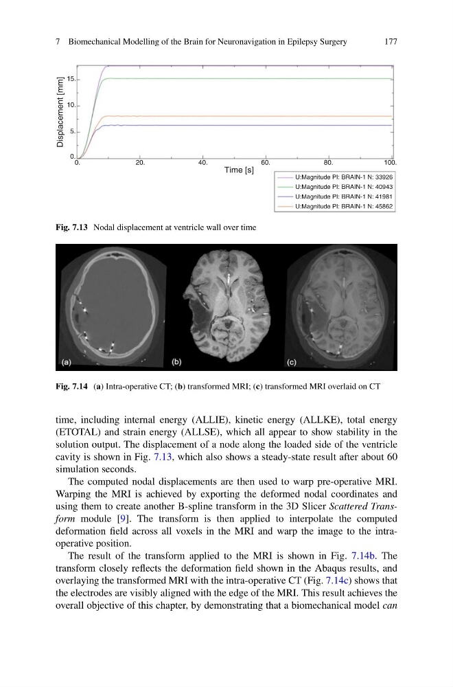
Fig. 7.14 (a) Intra-operative CT; (b) transformed MRI; (c) transformed MRI overlaid on CT
time, including internal energy (ALLIE), kinetic energy (ALLKE), total energy
(ETOTAL) and strain energy (ALLSE), which all appear to show stability in the
solution output. The displacement of a node along the loaded side of the ventricle
cavity is shown in Fig. 7.13, which also shows a steady-state result after about 60
simulation seconds.
The computed nodal displacements are then used to warp pre-operative MRI.
Warping the MRI is achieved by exporting the deformed nodal coordinates and
using them to create another B-spline transform in the 3D Slicer Scattered Transform module [9]. The transform is then applied to interpolate the computed
deformation field across all voxels in the MRI and warp the image to the intraoperative position.
The result of the transform applied to the MRI is shown in Fig. 7.14b. The
transform closely reflects the deformation field shown in the Abaqus results, and
overlaying the transformed MRI with the intra-operative CT (Fig. 7.14c) shows that
the electrodes are visibly aligned with the edge of the MRI. This result achieves the
overall objective of this chapter, by demonstrating that a biomechanical model can
177
Displacement [mm]
Time [s]
15.
10.
5.
0.
0.
20.
40.
60.
80.
U:Magnitude PI: BRAIN-1 N: 33926
U:Magnitude PI: BRAIN-1 N: 40943
U:Magnitude PI: BRAIN-1 N: 41981
U:Magnitude PI: BRAIN-1 N: 45862
100.
Fig. 7.13 Nodal displacement at ventricle wall over time
Fig. 7.14 (a) Intra-operative CT; (b) transformed MRI; (c) transformed MRI overlaid on CT
time, including internal energy (ALLIE), kinetic energy (ALLKE), total energy
(ETOTAL) and strain energy (ALLSE), which all appear to show stability in the
solution output. The displacement of a node along the loaded side of the ventricle
cavity is shown in Fig. 7.13, which also shows a steady-state result after about 60
simulation seconds.
The computed nodal displacements are then used to warp pre-operative MRI.
Warping the MRI is achieved by exporting the deformed nodal coordinates and
using them to create another B-spline transform in the 3D Slicer Scattered Transform module [9]. The transform is then applied to interpolate the computed
deformation field across all voxels in the MRI and warp the image to the intraoperative position.
The result of the transform applied to the MRI is shown in Fig. 7.14b. The
transform closely reflects the deformation field shown in the Abaqus results, and
overlaying the transformed MRI with the intra-operative CT (Fig. 7.14c) shows that
the electrodes are visibly aligned with the edge of the MRI. This result achieves the
overall objective of this chapter, by demonstrating that a biomechanical model can