

7 Biomechanical Modelling of the Brain for Neuronavigation in Epilepsy Surgery
175
7.3 Results
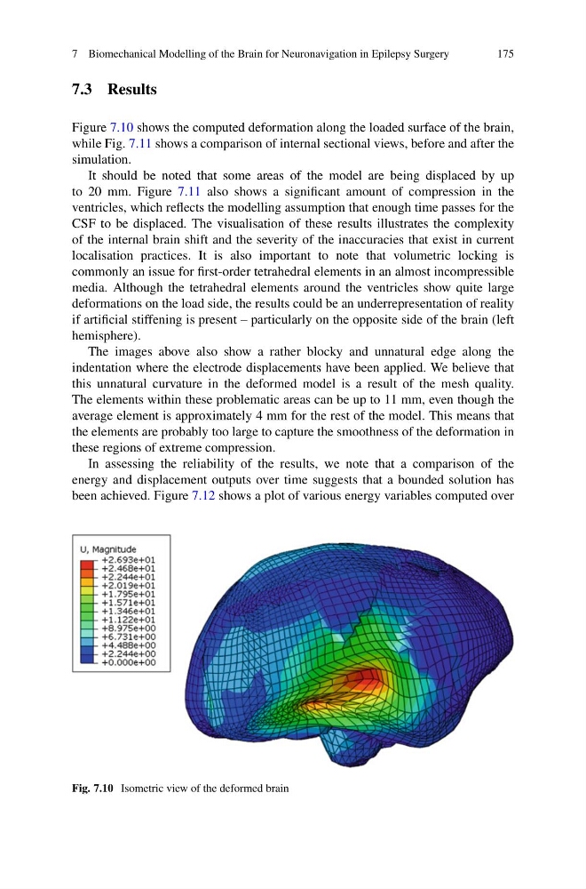
Figure 7.10 shows the computed deformation along the loaded surface of the brain,
while Fig. 7.11 shows a comparison of internal sectional views, before and after the
simulation.
It should be noted that some areas of the model are being displaced by up
to 20 mm. Figure 7.11 also shows a significant amount of compression in the
ventricles, which reflects the modelling assumption that enough time passes for the
CSF to be displaced. The visualisation of these results illustrates the complexity
of the internal brain shift and the severity of the inaccuracies that exist in current
localisation practices. It is also important to note that volumetric locking is
commonly an issue for first-order tetrahedral elements in an almost incompressible
media. Although the tetrahedral elements around the ventricles show quite large
deformations on the load side, the results could be an underrepresentation of reality
if artificial stiffening is present – particularly on the opposite side of the brain (left
hemisphere).
The images above also show a rather blocky and unnatural edge along the
indentation where the electrode displacements have been applied. We believe that
this unnatural curvature in the deformed model is a result of the mesh quality.
The elements within these problematic areas can be up to 11 mm, even though the
average element is approximately 4 mm for the rest of the model. This means that
the elements are probably too large to capture the smoothness of the deformation in
these regions of extreme compression.
In assessing the reliability of the results, we note that a comparison of the
energy and displacement outputs over time suggests that a bounded solution has
been achieved. Figure 7.12 shows a plot of various energy variables computed over
Fig. 7.10 Isometric view of the deformed brain
175
7.3 Results
Figure 7.10 shows the computed deformation along the loaded surface of the brain,
while Fig. 7.11 shows a comparison of internal sectional views, before and after the
simulation.
It should be noted that some areas of the model are being displaced by up
to 20 mm. Figure 7.11 also shows a significant amount of compression in the
ventricles, which reflects the modelling assumption that enough time passes for the
CSF to be displaced. The visualisation of these results illustrates the complexity
of the internal brain shift and the severity of the inaccuracies that exist in current
localisation practices. It is also important to note that volumetric locking is
commonly an issue for first-order tetrahedral elements in an almost incompressible
media. Although the tetrahedral elements around the ventricles show quite large
deformations on the load side, the results could be an underrepresentation of reality
if artificial stiffening is present – particularly on the opposite side of the brain (left
hemisphere).
The images above also show a rather blocky and unnatural edge along the
indentation where the electrode displacements have been applied. We believe that
this unnatural curvature in the deformed model is a result of the mesh quality.
The elements within these problematic areas can be up to 11 mm, even though the
average element is approximately 4 mm for the rest of the model. This means that
the elements are probably too large to capture the smoothness of the deformation in
these regions of extreme compression.
In assessing the reliability of the results, we note that a comparison of the
energy and displacement outputs over time suggests that a bounded solution has
been achieved. Figure 7.12 shows a plot of various energy variables computed over
Fig. 7.10 Isometric view of the deformed brain