

4.3 Reflection of a Plane Wave from a Layer with a Slowly Varying Thickness
71
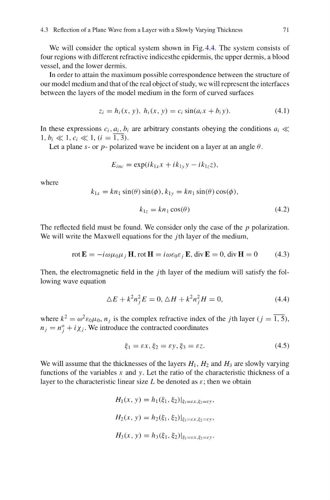
We will consider the optical system shown in Fig. 4.4. The system consists of
four regions with different refractive indicesthe epidermis, the upper dermis, a blood
vessel, and the lower dermis.
In order to attain the maximum possible correspondence between the structure of
our model medium and that of the real object of study, we will represent the interfaces
between the layers of the model medium in the form of curved surfaces
z i = h i (x, y), h i (x, y) = c i sin(a i x + b i y).
(4.1)
In these expressions c i , a i , b i are arbitrary constants obeying the conditions a i
1, b i 1, c i 1, (i = 1, 3).
Let a plane s- or p- polarized wave be incident on a layer at an angle θ .
E inc = exp(ik 1x x + ik 1y y − ik 1z z),
where
k 1x = kn 1 sin(θ ) sin(φ), k 1y = kn 1 sin(θ ) cos(φ),
k 1z = kn 1 cos(θ )
(4.2)
The reflected field must be found. We consider only the case of the p polarization.
We will write the Maxwell equations for the jth layer of the medium,
rot E = −iωμ 0 μ j H, rot H = iωε 0 ε j E, div E = 0, div H = 0
(4.3)
Then, the electromagnetic field in the jth layer of the medium will satisfy the following wave equation
E + k
2 n
2
j E = 0, H + k
2 n
2
j H = 0,
(4.4)
where k
2
= ω
2
ε 0 μ 0 , n j is the complex refractive index of the jth layer ( j = 1, 5),
n j = n
o
j + iχ j . We introduce the contracted coordinates
ξ 1 = εx, ξ 2 = εy, ξ 3 = εz.
(4.5)
We will assume that the thicknesses of the layers H 1 , H 2 and H 3 are slowly varying
functions of the variables x and y. Let the ratio of the characteristic thickness of a
layer to the characteristic linear size L be denoted as ε; then we obtain
H 1 (x, y) = h 1 (ξ 1 , ξ 2 )| ξ 1 =εx,ξ 2 =εy ,
H 2 (x, y) = h 2 (ξ 1 , ξ 2 )| ξ 1 =εx,ξ 2 =εy ,
H 3 (x, y) = h 3 (ξ 1 , ξ 2 )| ξ 1 =εx,ξ 2 =εy .
71
We will consider the optical system shown in Fig. 4.4. The system consists of
four regions with different refractive indicesthe epidermis, the upper dermis, a blood
vessel, and the lower dermis.
In order to attain the maximum possible correspondence between the structure of
our model medium and that of the real object of study, we will represent the interfaces
between the layers of the model medium in the form of curved surfaces
z i = h i (x, y), h i (x, y) = c i sin(a i x + b i y).
(4.1)
In these expressions c i , a i , b i are arbitrary constants obeying the conditions a i
1, b i 1, c i 1, (i = 1, 3).
Let a plane s- or p- polarized wave be incident on a layer at an angle θ .
E inc = exp(ik 1x x + ik 1y y − ik 1z z),
where
k 1x = kn 1 sin(θ ) sin(φ), k 1y = kn 1 sin(θ ) cos(φ),
k 1z = kn 1 cos(θ )
(4.2)
The reflected field must be found. We consider only the case of the p polarization.
We will write the Maxwell equations for the jth layer of the medium,
rot E = −iωμ 0 μ j H, rot H = iωε 0 ε j E, div E = 0, div H = 0
(4.3)
Then, the electromagnetic field in the jth layer of the medium will satisfy the following wave equation
E + k
2 n
2
j E = 0, H + k
2 n
2
j H = 0,
(4.4)
where k
2
= ω
2
ε 0 μ 0 , n j is the complex refractive index of the jth layer ( j = 1, 5),
n j = n
o
j + iχ j . We introduce the contracted coordinates
ξ 1 = εx, ξ 2 = εy, ξ 3 = εz.
(4.5)
We will assume that the thicknesses of the layers H 1 , H 2 and H 3 are slowly varying
functions of the variables x and y. Let the ratio of the characteristic thickness of a
layer to the characteristic linear size L be denoted as ε; then we obtain
H 1 (x, y) = h 1 (ξ 1 , ξ 2 )| ξ 1 =εx,ξ 2 =εy ,
H 2 (x, y) = h 2 (ξ 1 , ξ 2 )| ξ 1 =εx,ξ 2 =εy ,
H 3 (x, y) = h 3 (ξ 1 , ξ 2 )| ξ 1 =εx,ξ 2 =εy .