

6
C.-H. Im
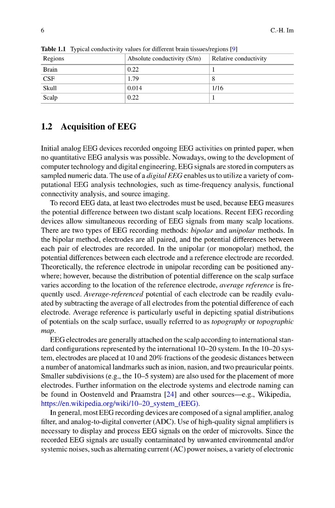
Table 1.1 Typical conductivity values for different brain tissues/regions [9]
Regions
Absolute conductivity (S/m)
Relative conductivity
Brain
0.22
1
CSF
1.79
8
Skull
0.014
1/16
Scalp
0.22
1
1.2 Acquisition of EEG
Initial analog EEG devices recorded ongoing EEG activities on printed paper, when
no quantitative EEG analysis was possible. Nowadays, owing to the development of
computer technology and digital engineering, EEG signals are stored in computers as
sampled numeric data. The use of a digital EEG enables us to utilize a variety of computational EEG analysis technologies, such as time-frequency analysis, functional
connectivity analysis, and source imaging.
To record EEG data, at least two electrodes must be used, because EEG measures
the potential difference between two distant scalp locations. Recent EEG recording
devices allow simultaneous recording of EEG signals from many scalp locations.
There are two types of EEG recording methods: bipolar and unipolar methods. In
the bipolar method, electrodes are all paired, and the potential differences between
each pair of electrodes are recorded. In the unipolar (or monopolar) method, the
potential differences between each electrode and a reference electrode are recorded.
Theoretically, the reference electrode in unipolar recording can be positioned anywhere; however, because the distribution of potential difference on the scalp surface
varies according to the location of the reference electrode, average reference is frequently used. Average-referenced potential of each electrode can be readily evaluated by subtracting the average of all electrodes from the potential difference of each
electrode. Average reference is particularly useful in depicting spatial distributions
of potentials on the scalp surface, usually referred to as topography or topographic
map.
EEG electrodes are generally attached on the scalp according to international standard configurations represented by the international 10–20 system. In the 10–20 system, electrodes are placed at 10 and 20% fractions of the geodesic distances between
a number of anatomical landmarks such as inion, nasion, and two preauricular points.
Smaller subdivisions (e.g., the 10–5 system) are also used for the placement of more
electrodes. Further information on the electrode systems and electrode naming can
be found in Oostenveld and Praamstra [24] and other sources—e.g., Wikipedia,
https://en.wikipedia.org/wiki/10–20_system_(EEG).
In general, most EEG recording devices are composed of a signal amplifier, analog
filter, and analog-to-digital converter (ADC). Use of high-quality signal amplifiers is
necessary to display and process EEG signals on the order of microvolts. Since the
recorded EEG signals are usually contaminated by unwanted environmental and/or
systemic noises, such as alternating current (AC) power noises, a variety of electronic
C.-H. Im
Table 1.1 Typical conductivity values for different brain tissues/regions [9]
Regions
Absolute conductivity (S/m)
Relative conductivity
Brain
0.22
1
CSF
1.79
8
Skull
0.014
1/16
Scalp
0.22
1
1.2 Acquisition of EEG
Initial analog EEG devices recorded ongoing EEG activities on printed paper, when
no quantitative EEG analysis was possible. Nowadays, owing to the development of
computer technology and digital engineering, EEG signals are stored in computers as
sampled numeric data. The use of a digital EEG enables us to utilize a variety of computational EEG analysis technologies, such as time-frequency analysis, functional
connectivity analysis, and source imaging.
To record EEG data, at least two electrodes must be used, because EEG measures
the potential difference between two distant scalp locations. Recent EEG recording
devices allow simultaneous recording of EEG signals from many scalp locations.
There are two types of EEG recording methods: bipolar and unipolar methods. In
the bipolar method, electrodes are all paired, and the potential differences between
each pair of electrodes are recorded. In the unipolar (or monopolar) method, the
potential differences between each electrode and a reference electrode are recorded.
Theoretically, the reference electrode in unipolar recording can be positioned anywhere; however, because the distribution of potential difference on the scalp surface
varies according to the location of the reference electrode, average reference is frequently used. Average-referenced potential of each electrode can be readily evaluated by subtracting the average of all electrodes from the potential difference of each
electrode. Average reference is particularly useful in depicting spatial distributions
of potentials on the scalp surface, usually referred to as topography or topographic
map.
EEG electrodes are generally attached on the scalp according to international standard configurations represented by the international 10–20 system. In the 10–20 system, electrodes are placed at 10 and 20% fractions of the geodesic distances between
a number of anatomical landmarks such as inion, nasion, and two preauricular points.
Smaller subdivisions (e.g., the 10–5 system) are also used for the placement of more
electrodes. Further information on the electrode systems and electrode naming can
be found in Oostenveld and Praamstra [24] and other sources—e.g., Wikipedia,
https://en.wikipedia.org/wiki/10–20_system_(EEG).
In general, most EEG recording devices are composed of a signal amplifier, analog
filter, and analog-to-digital converter (ADC). Use of high-quality signal amplifiers is
necessary to display and process EEG signals on the order of microvolts. Since the
recorded EEG signals are usually contaminated by unwanted environmental and/or
systemic noises, such as alternating current (AC) power noises, a variety of electronic