

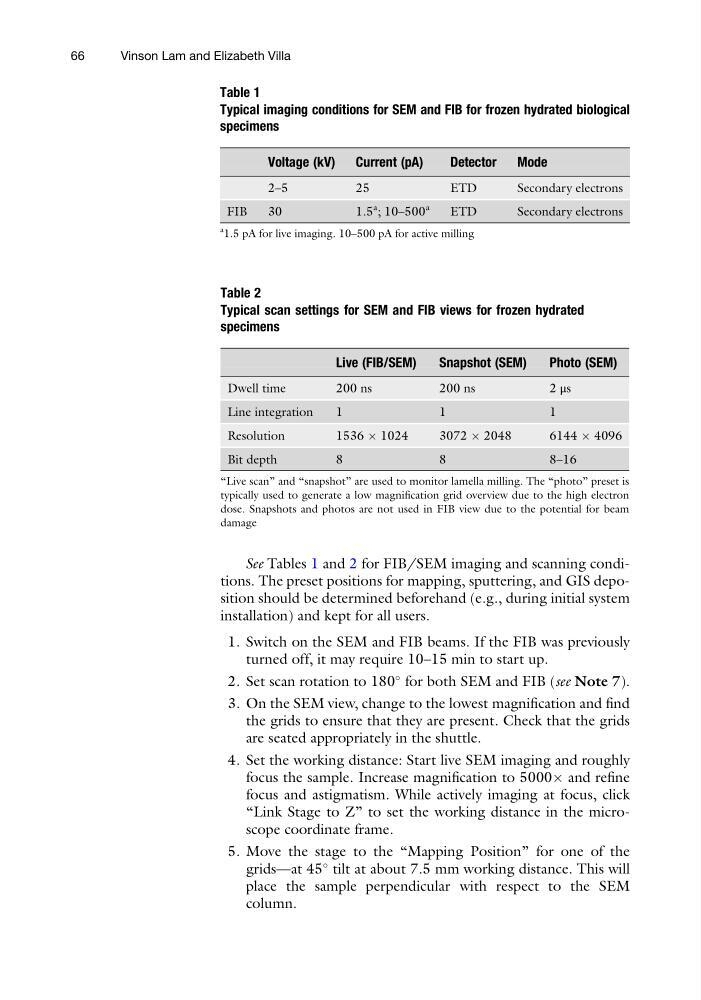
See Tables 1 and 2 for FIB/SEM imaging and scanning conditions. The preset positions for mapping, sputtering, and GIS deposition should be determined beforehand (e.g., during initial system
installation) and kept for all users.
1. Switch on the SEM and FIB beams. If the FIB was previously
turned off, it may require 10–15 min to start up.
2. Set scan rotation to 180
for both SEM and FIB (see Note 7).
3. On the SEM view, change to the lowest magnification and find
the grids to ensure that they are present. Check that the grids
are seated appropriately in the shuttle.
4. Set the working distance: Start live SEM imaging and roughly
focus the sample. Increase magnification to 5000Â and refine
focus and astigmatism. While actively imaging at focus, click
“Link Stage to Z” to set the working distance in the microscope coordinate frame.
5. Move the stage to the “Mapping Position” for one of the
grids—at 45
tilt at about 7.5 mm working distance. This will
place the sample perpendicular with respect to the SEM
column.
Table 1
Typical imaging conditions for SEM and FIB for frozen hydrated biological
specimens
Voltage (kV) Current (pA)
Detector Mode
2–5
25
ETD
Secondary electrons
FIB
30
1.5
a ; 10–500
a
ETD
Secondary electrons
a
1.5 pA for live imaging. 10–500 pA for active milling
Table 2
Typical scan settings for SEM and FIB views for frozen hydrated
specimens
Live (FIB/SEM)
Snapshot (SEM)
Photo (SEM)
Dwell time
200 ns
200 ns
2 μs
Line integration
1
1
1
Resolution
1536 Â 1024
3072 Â 2048
6144 Â 4096
Bit depth
8
8
8–16
“Live scan” and “snapshot” are used to monitor lamella milling. The “photo” preset is
typically used to generate a low magnification grid overview due to the high electron
dose. Snapshots and photos are not used in FIB view due to the potential for beam
damage
66
Vinson Lam and Elizabeth Villa
installation) and kept for all users.
1. Switch on the SEM and FIB beams. If the FIB was previously
turned off, it may require 10–15 min to start up.
2. Set scan rotation to 180
for both SEM and FIB (see Note 7).
3. On the SEM view, change to the lowest magnification and find
the grids to ensure that they are present. Check that the grids
are seated appropriately in the shuttle.
4. Set the working distance: Start live SEM imaging and roughly
focus the sample. Increase magnification to 5000Â and refine
focus and astigmatism. While actively imaging at focus, click
“Link Stage to Z” to set the working distance in the microscope coordinate frame.
5. Move the stage to the “Mapping Position” for one of the
grids—at 45
tilt at about 7.5 mm working distance. This will
place the sample perpendicular with respect to the SEM
column.
Table 1
Typical imaging conditions for SEM and FIB for frozen hydrated biological
specimens
Voltage (kV) Current (pA)
Detector Mode
2–5
25
ETD
Secondary electrons
FIB
30
1.5
a ; 10–500
a
ETD
Secondary electrons
a
1.5 pA for live imaging. 10–500 pA for active milling
Table 2
Typical scan settings for SEM and FIB views for frozen hydrated
specimens
Live (FIB/SEM)
Snapshot (SEM)
Photo (SEM)
Dwell time
200 ns
200 ns
2 μs
Line integration
1
1
1
Resolution
1536 Â 1024
3072 Â 2048
6144 Â 4096
Bit depth
8
8
8–16
“Live scan” and “snapshot” are used to monitor lamella milling. The “photo” preset is
typically used to generate a low magnification grid overview due to the high electron
dose. Snapshots and photos are not used in FIB view due to the potential for beam
damage
66
Vinson Lam and Elizabeth Villa