

The shuttle holds the grids at a 45
angle relative to the
vertically mounted SEM column (Figs. 2b and 3e). During operation, the stage may be tilted anywhere from 0
to 45
relative to the
horizontal stage position. The FIB column and platinum GIS
needle are mounted 52
relative to the SEM (Fig. 2c). The stage
is capable of XYZ positioning as well as rotation about the Z-axis,
and tilt about the X-axis (the direction of sample insertion). Consequently, there is one XYZ position that brings the milling target
to the beam-coincidence point. The rotation angle is determined
by the mounting position of the FIB column, and tilt is determined
by the specific sample and lamella requirements.
1.1.3 Stage Temperature
Control
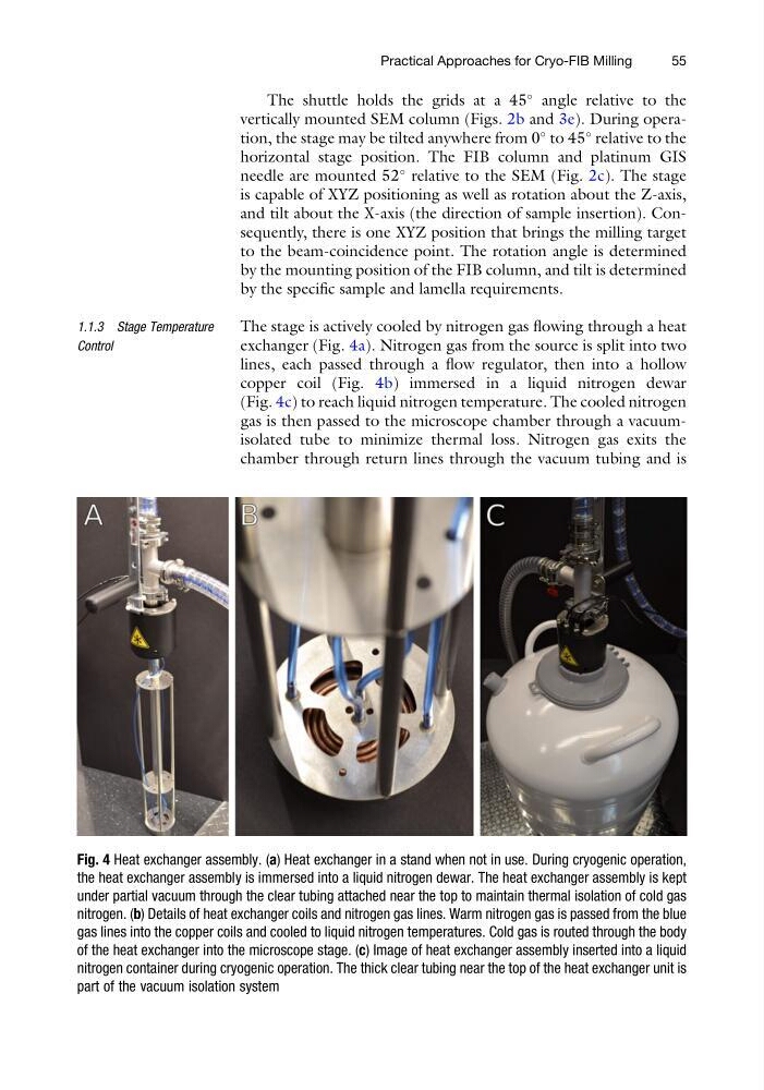
The stage is actively cooled by nitrogen gas flowing through a heat
exchanger (Fig. 4a). Nitrogen gas from the source is split into two
lines, each passed through a flow regulator, then into a hollow
copper coil (Fig. 4b) immersed in a liquid nitrogen dewar
(Fig. 4c) to reach liquid nitrogen temperature. The cooled nitrogen
gas is then passed to the microscope chamber through a vacuumisolated tube to minimize thermal loss. Nitrogen gas exits the
chamber through return lines through the vacuum tubing and is
Fig. 4 Heat exchanger assembly. (a) Heat exchanger in a stand when not in use. During cryogenic operation,
the heat exchanger assembly is immersed into a liquid nitrogen dewar. The heat exchanger assembly is kept
under partial vacuum through the clear tubing attached near the top to maintain thermal isolation of cold gas
nitrogen. (b) Details of heat exchanger coils and nitrogen gas lines. Warm nitrogen gas is passed from the blue
gas lines into the copper coils and cooled to liquid nitrogen temperatures. Cold gas is routed through the body
of the heat exchanger into the microscope stage. (c) Image of heat exchanger assembly inserted into a liquid
nitrogen container during cryogenic operation. The thick clear tubing near the top of the heat exchanger unit is
part of the vacuum isolation system
Practical Approaches for Cryo-FIB Milling
55
angle relative to the
vertically mounted SEM column (Figs. 2b and 3e). During operation, the stage may be tilted anywhere from 0
to 45
relative to the
horizontal stage position. The FIB column and platinum GIS
needle are mounted 52
relative to the SEM (Fig. 2c). The stage
is capable of XYZ positioning as well as rotation about the Z-axis,
and tilt about the X-axis (the direction of sample insertion). Consequently, there is one XYZ position that brings the milling target
to the beam-coincidence point. The rotation angle is determined
by the mounting position of the FIB column, and tilt is determined
by the specific sample and lamella requirements.
1.1.3 Stage Temperature
Control
The stage is actively cooled by nitrogen gas flowing through a heat
exchanger (Fig. 4a). Nitrogen gas from the source is split into two
lines, each passed through a flow regulator, then into a hollow
copper coil (Fig. 4b) immersed in a liquid nitrogen dewar
(Fig. 4c) to reach liquid nitrogen temperature. The cooled nitrogen
gas is then passed to the microscope chamber through a vacuumisolated tube to minimize thermal loss. Nitrogen gas exits the
chamber through return lines through the vacuum tubing and is
Fig. 4 Heat exchanger assembly. (a) Heat exchanger in a stand when not in use. During cryogenic operation,
the heat exchanger assembly is immersed into a liquid nitrogen dewar. The heat exchanger assembly is kept
under partial vacuum through the clear tubing attached near the top to maintain thermal isolation of cold gas
nitrogen. (b) Details of heat exchanger coils and nitrogen gas lines. Warm nitrogen gas is passed from the blue
gas lines into the copper coils and cooled to liquid nitrogen temperatures. Cold gas is routed through the body
of the heat exchanger into the microscope stage. (c) Image of heat exchanger assembly inserted into a liquid
nitrogen container during cryogenic operation. The thick clear tubing near the top of the heat exchanger unit is
part of the vacuum isolation system
Practical Approaches for Cryo-FIB Milling
55