

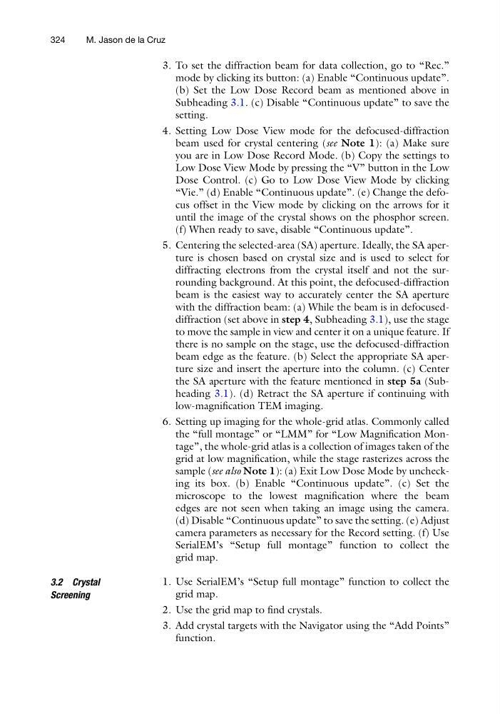
3. To set the diffraction beam for data collection, go to “Rec.”
mode by clicking its button: (a) Enable “Continuous update”.
(b) Set the Low Dose Record beam as mentioned above in
Subheading 3.1. (c) Disable “Continuous update” to save the
setting.
4. Setting Low Dose View mode for the defocused-diffraction
beam used for crystal centering (see Note 1): (a) Make sure
you are in Low Dose Record Mode. (b) Copy the settings to
Low Dose View Mode by pressing the “V” button in the Low
Dose Control. (c) Go to Low Dose View Mode by clicking
“Vie.” (d) Enable “Continuous update”. (e) Change the defocus offset in the View mode by clicking on the arrows for it
until the image of the crystal shows on the phosphor screen.
(f) When ready to save, disable “Continuous update”.
5. Centering the selected-area (SA) aperture. Ideally, the SA aperture is chosen based on crystal size and is used to select for
diffracting electrons from the crystal itself and not the surrounding background. At this point, the defocused-diffraction
beam is the easiest way to accurately center the SA aperture
with the diffraction beam: (a) While the beam is in defocuseddiffraction (set above in step 4, Subheading 3.1), use the stage
to move the sample in view and center it on a unique feature. If
there is no sample on the stage, use the defocused-diffraction
beam edge as the feature. (b) Select the appropriate SA aperture size and insert the aperture into the column. (c) Center
the SA aperture with the feature mentioned in step 5a (Subheading 3.1). (d) Retract the SA aperture if continuing with
low-magnification TEM imaging.
6. Setting up imaging for the whole-grid atlas. Commonly called
the “full montage” or “LMM” for “Low Magnification Montage”, the whole-grid atlas is a collection of images taken of the
grid at low magnification, while the stage rasterizes across the
sample (see also Note 1): (a) Exit Low Dose Mode by unchecking its box. (b) Enable “Continuous update”. (c) Set the
microscope to the lowest magnification where the beam
edges are not seen when taking an image using the camera.
(d) Disable “Continuous update” to save the setting. (e) Adjust
camera parameters as necessary for the Record setting. (f) Use
SerialEM’s “Setup full montage” function to collect the
grid map.
3.2 Crystal
Screening
1. Use SerialEM’s “Setup full montage” function to collect the
grid map.
2. Use the grid map to find crystals.
3. Add crystal targets with the Navigator using the “Add Points”
function.
324
M. Jason de la Cruz
mode by clicking its button: (a) Enable “Continuous update”.
(b) Set the Low Dose Record beam as mentioned above in
Subheading 3.1. (c) Disable “Continuous update” to save the
setting.
4. Setting Low Dose View mode for the defocused-diffraction
beam used for crystal centering (see Note 1): (a) Make sure
you are in Low Dose Record Mode. (b) Copy the settings to
Low Dose View Mode by pressing the “V” button in the Low
Dose Control. (c) Go to Low Dose View Mode by clicking
“Vie.” (d) Enable “Continuous update”. (e) Change the defocus offset in the View mode by clicking on the arrows for it
until the image of the crystal shows on the phosphor screen.
(f) When ready to save, disable “Continuous update”.
5. Centering the selected-area (SA) aperture. Ideally, the SA aperture is chosen based on crystal size and is used to select for
diffracting electrons from the crystal itself and not the surrounding background. At this point, the defocused-diffraction
beam is the easiest way to accurately center the SA aperture
with the diffraction beam: (a) While the beam is in defocuseddiffraction (set above in step 4, Subheading 3.1), use the stage
to move the sample in view and center it on a unique feature. If
there is no sample on the stage, use the defocused-diffraction
beam edge as the feature. (b) Select the appropriate SA aperture size and insert the aperture into the column. (c) Center
the SA aperture with the feature mentioned in step 5a (Subheading 3.1). (d) Retract the SA aperture if continuing with
low-magnification TEM imaging.
6. Setting up imaging for the whole-grid atlas. Commonly called
the “full montage” or “LMM” for “Low Magnification Montage”, the whole-grid atlas is a collection of images taken of the
grid at low magnification, while the stage rasterizes across the
sample (see also Note 1): (a) Exit Low Dose Mode by unchecking its box. (b) Enable “Continuous update”. (c) Set the
microscope to the lowest magnification where the beam
edges are not seen when taking an image using the camera.
(d) Disable “Continuous update” to save the setting. (e) Adjust
camera parameters as necessary for the Record setting. (f) Use
SerialEM’s “Setup full montage” function to collect the
grid map.
3.2 Crystal
Screening
1. Use SerialEM’s “Setup full montage” function to collect the
grid map.
2. Use the grid map to find crystals.
3. Add crystal targets with the Navigator using the “Add Points”
function.
324
M. Jason de la Cruz