

9. Please refer to the user guidelines provided by FEI/Thermo
Fisher Scientific. Clipping grids under liquid nitrogen may
result in physical damage to the grid. This will manifest as
large cracks within grid squares or microfractures within holes
containing vitreous ice that “pop” immediately upon illumination. Therefore, it is recommended that grids are clipped under
nitrogen vapor rather than liquid nitrogen.
10. Micro probe mode uses the minicondenser lens located immediately above the upper pole piece of the objective lens to create
another crossover above the objective lens (Fig. 4). As a result,
parallel illumination in Nano probe mode will yield a much
smaller diameter beam (often >35% smaller) than what is
obtained using Micro probe mode when using the same C2
aperture, spot size, gun lens, and magnification (Fig. 4). However, alignment errors in Nano probe mode are accentuated
more so than would be observed in Micro probe mode.
11. The backlash of the stage will cause a jolting of the image upon
initialization of movement, so it is best to make adjustments to
Z-height during the smoother section of stage tilting motion.
12. This method can also prove to be very useful to quickly check if
the specimen is at eucentric height when diagnosing potential
column alignment issues.
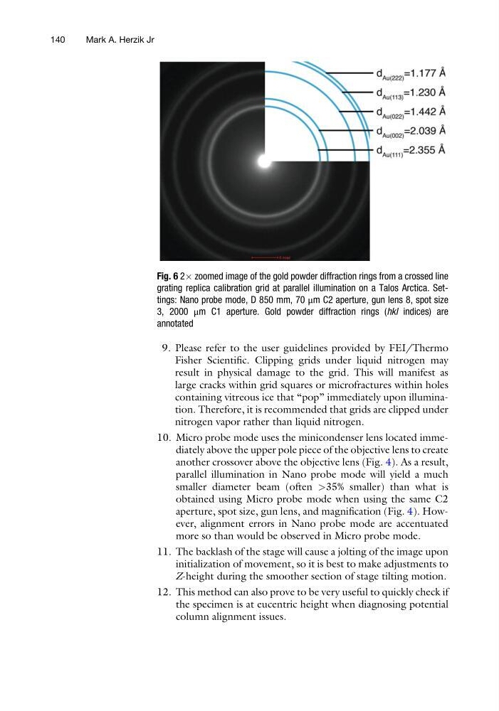
Fig. 6 2Â zoomed image of the gold powder diffraction rings from a crossed line
grating replica calibration grid at parallel illumination on a Talos Arctica. Settings: Nano probe mode, D 850 mm, 70 μm C2 aperture, gun lens 8, spot size
3, 2000 μm C1 aperture. Gold powder diffraction rings (hkl indices) are
annotated
140
Mark A. Herzik Jr
Fisher Scientific. Clipping grids under liquid nitrogen may
result in physical damage to the grid. This will manifest as
large cracks within grid squares or microfractures within holes
containing vitreous ice that “pop” immediately upon illumination. Therefore, it is recommended that grids are clipped under
nitrogen vapor rather than liquid nitrogen.
10. Micro probe mode uses the minicondenser lens located immediately above the upper pole piece of the objective lens to create
another crossover above the objective lens (Fig. 4). As a result,
parallel illumination in Nano probe mode will yield a much
smaller diameter beam (often >35% smaller) than what is
obtained using Micro probe mode when using the same C2
aperture, spot size, gun lens, and magnification (Fig. 4). However, alignment errors in Nano probe mode are accentuated
more so than would be observed in Micro probe mode.
11. The backlash of the stage will cause a jolting of the image upon
initialization of movement, so it is best to make adjustments to
Z-height during the smoother section of stage tilting motion.
12. This method can also prove to be very useful to quickly check if
the specimen is at eucentric height when diagnosing potential
column alignment issues.
Fig. 6 2Â zoomed image of the gold powder diffraction rings from a crossed line
grating replica calibration grid at parallel illumination on a Talos Arctica. Settings: Nano probe mode, D 850 mm, 70 μm C2 aperture, gun lens 8, spot size
3, 2000 μm C1 aperture. Gold powder diffraction rings (hkl indices) are
annotated
140
Mark A. Herzik Jr