

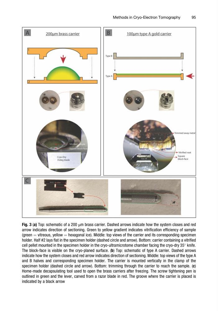
Fig. 3 (a) Top: schematic of a 200 μm brass carrier. Dashed arrows indicate how the system closes and red
arrow indicates direction of sectioning. Green to yellow gradient indicates vitrification efficiency of sample
(green ¼ vitreous, yellow ¼ hexagonal ice). Middle: top views of the carrier and its corresponding specimen
holder. Half #2 lays flat in the specimen holder (dashed circle and arrow). Bottom: carrier containing a vitrified
cell pellet mounted in the specimen holder in the cryo-ultramicrotome chamber facing the cryo-dry 35
knife.
The block-face is visible on the cryo-planed surface. (b) Top: schematic of type A carrier. Dashed arrows
indicate how the system closes and red arrow indicates direction of sectioning. Middle: top views of the type A
and B halves and corresponding specimen holder. The carrier is mounted vertically in the clamp of the
specimen holder (dashed circle and arrow). Bottom: trimming through the carrier to reach the sample. (c)
Home-made decapsulating tool used to open the brass carriers after freezing. The screw tightening pen is
outlined in green and the lever, carved from a razor blade in red. The groove where the carrier is placed is
indicated by a black arrow
Methods in Cryo-Electron Tomography
95
arrow indicates direction of sectioning. Green to yellow gradient indicates vitrification efficiency of sample
(green ¼ vitreous, yellow ¼ hexagonal ice). Middle: top views of the carrier and its corresponding specimen
holder. Half #2 lays flat in the specimen holder (dashed circle and arrow). Bottom: carrier containing a vitrified
cell pellet mounted in the specimen holder in the cryo-ultramicrotome chamber facing the cryo-dry 35
knife.
The block-face is visible on the cryo-planed surface. (b) Top: schematic of type A carrier. Dashed arrows
indicate how the system closes and red arrow indicates direction of sectioning. Middle: top views of the type A
and B halves and corresponding specimen holder. The carrier is mounted vertically in the clamp of the
specimen holder (dashed circle and arrow). Bottom: trimming through the carrier to reach the sample. (c)
Home-made decapsulating tool used to open the brass carriers after freezing. The screw tightening pen is
outlined in green and the lever, carved from a razor blade in red. The groove where the carrier is placed is
indicated by a black arrow
Methods in Cryo-Electron Tomography
95