

413
as data cubes, with x- and y-axes representing the spatial extent of the imaged area
and the z-axis representing the spectral response measured across the wavelength
range (Vane and Goetz 1988). Commonly used systems are push-broom and whiskbroom imagers, which are usually operated from a moving platform. Alternatively,
the imaged scene can move while the imaging spectrometer scans the samples,
which is, for example, possible using conveyor-belt-like setups in the laboratory.
It is important to know the footprint, or ground field of view (GFOV), of remote
sensing instruments. For nonimaging systems, the footprint equals the measured
area on the ground; for imaging systems, it determines image and pixel size. The
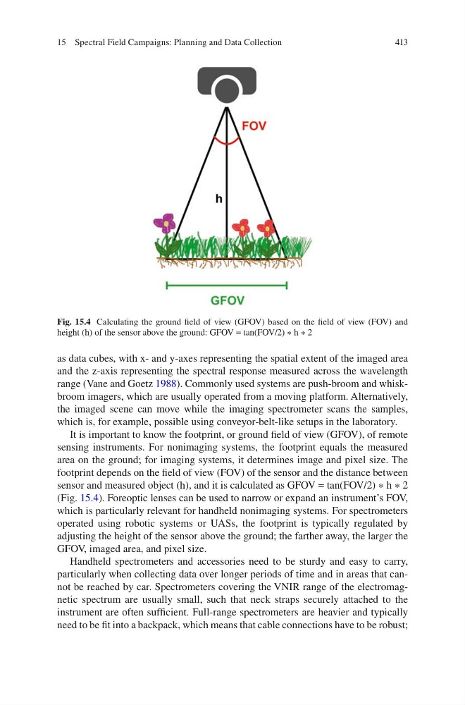
footprint depends on the field of view (FOV) of the sensor and the distance between
sensor and measured object (h), and it is calculated as GFOV = tan(FOV/2) ∗ h ∗ 2
(Fig. 15.4). Foreoptic lenses can be used to narrow or expand an instrument’s FOV,
which is particularly relevant for handheld nonimaging systems. For spectrometers
operated using robotic systems or UASs, the footprint is typically regulated by
adjusting the height of the sensor above the ground; the farther away, the larger the
GFOV, imaged area, and pixel size.
Handheld spectrometers and accessories need to be sturdy and easy to carry,
particularly when collecting data over longer periods of time and in areas that cannot be reached by car. Spectrometers covering the VNIR range of the electromagnetic spectrum are usually small, such that neck straps securely attached to the
instrument are often sufficient. Full-range spectrometers are heavier and typically
need to be fit into a backpack, which means that cable connections have to be robust;
Fig. 15.4 Calculating the ground field of view (GFOV) based on the field of view (FOV) and
height (h) of the sensor above the ground: GFOV = tan(FOV/2) ∗ h ∗ 2
15 Spectral Field Campaigns: Planning and Data Collection
as data cubes, with x- and y-axes representing the spatial extent of the imaged area
and the z-axis representing the spectral response measured across the wavelength
range (Vane and Goetz 1988). Commonly used systems are push-broom and whiskbroom imagers, which are usually operated from a moving platform. Alternatively,
the imaged scene can move while the imaging spectrometer scans the samples,
which is, for example, possible using conveyor-belt-like setups in the laboratory.
It is important to know the footprint, or ground field of view (GFOV), of remote
sensing instruments. For nonimaging systems, the footprint equals the measured
area on the ground; for imaging systems, it determines image and pixel size. The
footprint depends on the field of view (FOV) of the sensor and the distance between
sensor and measured object (h), and it is calculated as GFOV = tan(FOV/2) ∗ h ∗ 2
(Fig. 15.4). Foreoptic lenses can be used to narrow or expand an instrument’s FOV,
which is particularly relevant for handheld nonimaging systems. For spectrometers
operated using robotic systems or UASs, the footprint is typically regulated by
adjusting the height of the sensor above the ground; the farther away, the larger the
GFOV, imaged area, and pixel size.
Handheld spectrometers and accessories need to be sturdy and easy to carry,
particularly when collecting data over longer periods of time and in areas that cannot be reached by car. Spectrometers covering the VNIR range of the electromagnetic spectrum are usually small, such that neck straps securely attached to the
instrument are often sufficient. Full-range spectrometers are heavier and typically
need to be fit into a backpack, which means that cable connections have to be robust;
Fig. 15.4 Calculating the ground field of view (GFOV) based on the field of view (FOV) and
height (h) of the sensor above the ground: GFOV = tan(FOV/2) ∗ h ∗ 2
15 Spectral Field Campaigns: Planning and Data Collection