

the sample suspension may contain reagents (elution peptides,
detergents, lipids) that compete with the protein for adsorption. In this case, these reagents have to be removed whenever
possible.
3.2 Vitrification
3.2.1 Preparation
of the Vitrified Suspension
The protocol presented here is adapted for a Vitrobot, but most of
the steps can be adjusted to a handmade plunger or a device from
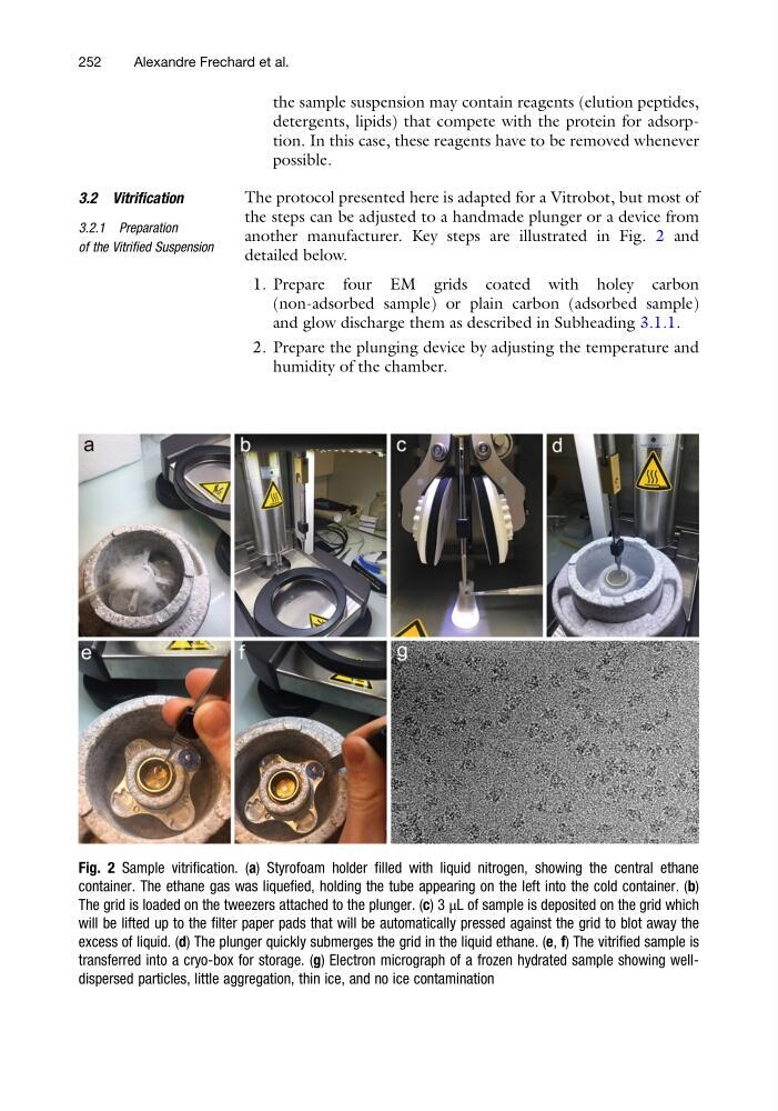
another manufacturer. Key steps are illustrated in Fig. 2 and
detailed below.
1. Prepare four EM grids coated with holey carbon
(non-adsorbed sample) or plain carbon (adsorbed sample)
and glow discharge them as described in Subheading 3.1.1.
2. Prepare the plunging device by adjusting the temperature and
humidity of the chamber.
Fig. 2 Sample vitrification. (a) Styrofoam holder filled with liquid nitrogen, showing the central ethane
container. The ethane gas was liquefied, holding the tube appearing on the left into the cold container. (b)
The grid is loaded on the tweezers attached to the plunger. (c) 3 μL of sample is deposited on the grid which
will be lifted up to the filter paper pads that will be automatically pressed against the grid to blot away the
excess of liquid. (d) The plunger quickly submerges the grid in the liquid ethane. (e, f) The vitrified sample is
transferred into a cryo-box for storage. (g) Electron micrograph of a frozen hydrated sample showing welldispersed particles, little aggregation, thin ice, and no ice contamination
252
Alexandre Frechard et al.
detergents, lipids) that compete with the protein for adsorption. In this case, these reagents have to be removed whenever
possible.
3.2 Vitrification
3.2.1 Preparation
of the Vitrified Suspension
The protocol presented here is adapted for a Vitrobot, but most of
the steps can be adjusted to a handmade plunger or a device from
another manufacturer. Key steps are illustrated in Fig. 2 and
detailed below.
1. Prepare four EM grids coated with holey carbon
(non-adsorbed sample) or plain carbon (adsorbed sample)
and glow discharge them as described in Subheading 3.1.1.
2. Prepare the plunging device by adjusting the temperature and
humidity of the chamber.
Fig. 2 Sample vitrification. (a) Styrofoam holder filled with liquid nitrogen, showing the central ethane
container. The ethane gas was liquefied, holding the tube appearing on the left into the cold container. (b)
The grid is loaded on the tweezers attached to the plunger. (c) 3 μL of sample is deposited on the grid which
will be lifted up to the filter paper pads that will be automatically pressed against the grid to blot away the
excess of liquid. (d) The plunger quickly submerges the grid in the liquid ethane. (e, f) The vitrified sample is
transferred into a cryo-box for storage. (g) Electron micrograph of a frozen hydrated sample showing welldispersed particles, little aggregation, thin ice, and no ice contamination
252
Alexandre Frechard et al.