

Adsorptive Impermeable Collector
reactor
barrier
shaft
Cout. GW entry
filter window
measurement
shaft
Drainage
shaft
Outlettreated water GW-pond west
former ground level
Silty, sd.
gravel
Quater+214.5 m SL
nary
Pannonian shales CONFINING LAYER
AC reactor
Scheme of
adsorptive
Hydraulic barrier
reactor
sampling ports
Unsaturated zone
Aquifer
Treated water
Contaminated water
Activated
G2-IN
G2-50%
carbon
G2-75%
Sampling ports
Controlled flooding
G2-OUT
AC filter
© Niederbacher
2001
292
Permeable Reactive Barrier
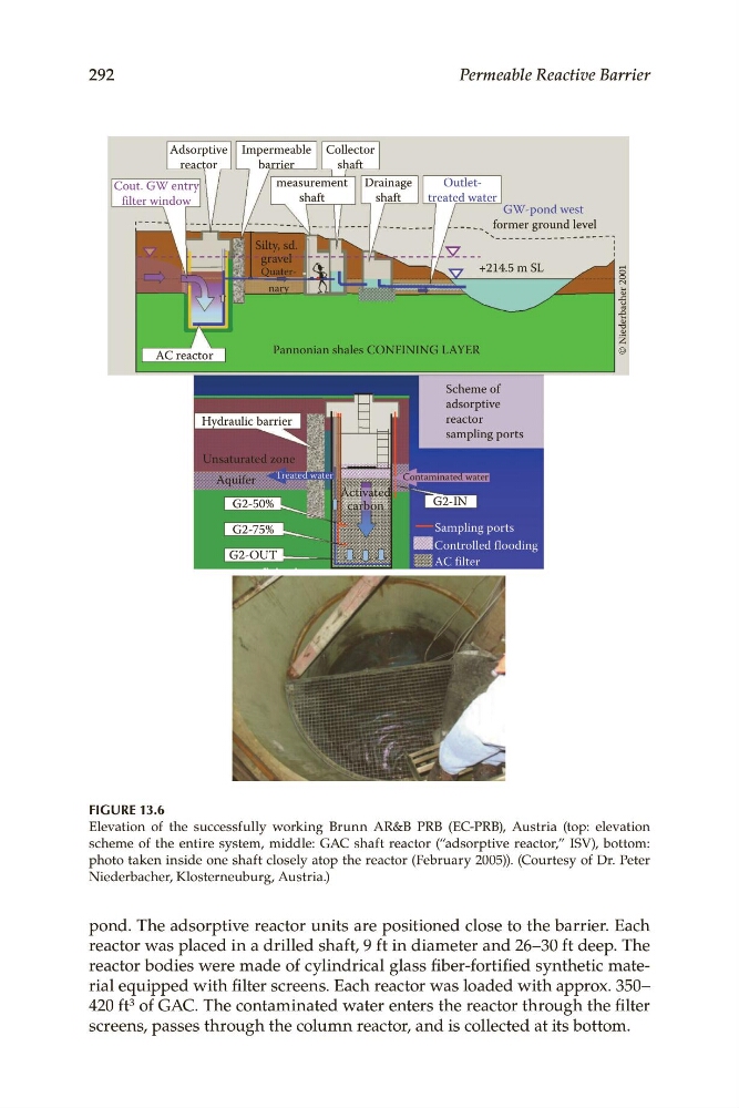
FIGURE 13.6
Elevation of the successfully working Brunn AR&B PRB (EC-PRB), Austria (top: elevation
scheme of the entire system, middle: GAC shaft reactor (“adsorptive reactor,” ISV), bottom:
photo taken inside one shaft closely atop the reactor (February 2005)). (Courtesy of Dr. Peter
Niederbacher, Klosterneuburg, Austria.)
pond. The adsorptive reactor units are positioned close to the barrier. Each
reactor was placed in a drilled shaft, 9 ft in diameter and 26–30 ft deep. The
reactor bodies were made of cylindrical glass fiber-fortified synthetic material equipped with filter screens. Each reactor was loaded with approx. 350–
420 ft 3 of GAC. The contaminated water enters the reactor through the filter
screens, passes through the column reactor, and is collected at its bottom.
reactor
barrier
shaft
Cout. GW entry
filter window
measurement
shaft
Drainage
shaft
Outlettreated water GW-pond west
former ground level
Silty, sd.
gravel
Quater+214.5 m SL
nary
Pannonian shales CONFINING LAYER
AC reactor
Scheme of
adsorptive
Hydraulic barrier
reactor
sampling ports
Unsaturated zone
Aquifer
Treated water
Contaminated water
Activated
G2-IN
G2-50%
carbon
G2-75%
Sampling ports
Controlled flooding
G2-OUT
AC filter
© Niederbacher
2001
292
Permeable Reactive Barrier
FIGURE 13.6
Elevation of the successfully working Brunn AR&B PRB (EC-PRB), Austria (top: elevation
scheme of the entire system, middle: GAC shaft reactor (“adsorptive reactor,” ISV), bottom:
photo taken inside one shaft closely atop the reactor (February 2005)). (Courtesy of Dr. Peter
Niederbacher, Klosterneuburg, Austria.)
pond. The adsorptive reactor units are positioned close to the barrier. Each
reactor was placed in a drilled shaft, 9 ft in diameter and 26–30 ft deep. The
reactor bodies were made of cylindrical glass fiber-fortified synthetic material equipped with filter screens. Each reactor was loaded with approx. 350–
420 ft 3 of GAC. The contaminated water enters the reactor through the filter
screens, passes through the column reactor, and is collected at its bottom.