

Performance
Limitations
Risk Lowering
Measures
Optimization Actions
Distribution of
reactants
Gas
dissolution
Dissolved
concentration
range of
reactants
Clogging,
permeability
losses
Bypassing of
groundwater
flow
Refining the injection
array density by gas
analysis-hydrogeological model
Variation of the injection
rate and pulses
Use of carrier gases
Use of a downstream
reaction zone
Forcing gas supply to
fine to medium
grained sediments
Limiting gas supply to
coarse sediments and
capture zones
Limiting reactant
concentrations
Optimization of the
geochemical state
Nutrient supply
Periodical redox state
changes (aerobic/
anaerobic)
Forcing autoregulation
Horizontal ROI dimensions and overlapping
Injection gallery sequences in flow direction
Identification of gas retardants
Injection below treatment layer
Injection rate (NDI) or pressure (HDI) change
Pulse frequency change
HDI–NDI combination
Hydraulic autoregulation by nitrogen clogging
Short-term reloading of reactants (e.g., oxygen)
Gas mixture supply (e.g., trace gases,
methane-air)
Macrodispersion mixing of reactants
Amplification of reaction length and time
Formation of dense gas networks with high
mass transfer interfaces
Homogenization of gas distribution
Prevention of inactive gas capture zones
Lowering gas saturation
Partial pressure variation of reactants
Aerosol or foam injection to control, e.g., pH,
Hardness and cometabolic degradation
Supply of higher oxidizers (e.g., H 2 O 2 )
Supply of gaseous and solid nutrients
(e.g., CH 4 , CO 2 , phosphate)
Lowering the injection cycle time
Increasing break periods
Avoiding the carrier gas supply
Demand-oriented reactant supply
Hydraulic forcing of bulk groundwater flow
due to local pumping or drainage
Source: Internal document of Sensatec GmbH, Kiel. With permission.
201
Reactive (Oxygen) Gas Barrier and Zone Technologies
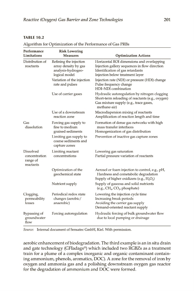
TABLE 10.2
Algorithm for Optimization of the Performance of Gas PRBs
aerobic enhancement of biodegradation. The third example is an in situ drain
and gate technology (GFIadags ® ) which included two RGBZs as a treatment
train for a plume of a complex inorganic and organic contaminant containing ammonium, phenols, aromatics, DOC). A zone for the removal of iron by
oxygen and ammonia gas and a polishing downstream oxygen gas reactor
for the degradation of ammonium and DOC were formed.
Limitations
Risk Lowering
Measures
Optimization Actions
Distribution of
reactants
Gas
dissolution
Dissolved
concentration
range of
reactants
Clogging,
permeability
losses
Bypassing of
groundwater
flow
Refining the injection
array density by gas
analysis-hydrogeological model
Variation of the injection
rate and pulses
Use of carrier gases
Use of a downstream
reaction zone
Forcing gas supply to
fine to medium
grained sediments
Limiting gas supply to
coarse sediments and
capture zones
Limiting reactant
concentrations
Optimization of the
geochemical state
Nutrient supply
Periodical redox state
changes (aerobic/
anaerobic)
Forcing autoregulation
Horizontal ROI dimensions and overlapping
Injection gallery sequences in flow direction
Identification of gas retardants
Injection below treatment layer
Injection rate (NDI) or pressure (HDI) change
Pulse frequency change
HDI–NDI combination
Hydraulic autoregulation by nitrogen clogging
Short-term reloading of reactants (e.g., oxygen)
Gas mixture supply (e.g., trace gases,
methane-air)
Macrodispersion mixing of reactants
Amplification of reaction length and time
Formation of dense gas networks with high
mass transfer interfaces
Homogenization of gas distribution
Prevention of inactive gas capture zones
Lowering gas saturation
Partial pressure variation of reactants
Aerosol or foam injection to control, e.g., pH,
Hardness and cometabolic degradation
Supply of higher oxidizers (e.g., H 2 O 2 )
Supply of gaseous and solid nutrients
(e.g., CH 4 , CO 2 , phosphate)
Lowering the injection cycle time
Increasing break periods
Avoiding the carrier gas supply
Demand-oriented reactant supply
Hydraulic forcing of bulk groundwater flow
due to local pumping or drainage
Source: Internal document of Sensatec GmbH, Kiel. With permission.
201
Reactive (Oxygen) Gas Barrier and Zone Technologies
TABLE 10.2
Algorithm for Optimization of the Performance of Gas PRBs
aerobic enhancement of biodegradation. The third example is an in situ drain
and gate technology (GFIadags ® ) which included two RGBZs as a treatment
train for a plume of a complex inorganic and organic contaminant containing ammonium, phenols, aromatics, DOC). A zone for the removal of iron by
oxygen and ammonia gas and a polishing downstream oxygen gas reactor
for the degradation of ammonium and DOC were formed.