

192 Ground improvement by deep vibratory methods
Alternatively, liquid concrete can be pumped through a pipe attached to
the vibrator delivering it directly to the vibrator point when the final depth
has been reached. Vibrator together with gravel or concrete pipe displaces
the native soil leaving behind a more or less cylindrical hollow space which
is filled with concrete in a controlled way as the vibrator is withdrawn.
vibro concrete column cross sections constructed in this way are generally
oval shaped with dimensions of ca. 30 × 50 cm. When the concrete is cured,
these columns, or rigid inclusions as they are sometimes called, carry loads
in the same manner as end bearing small diameter unreinforced concrete
piles, supported by skin friction and end bearing in stiffer soils. Their bearing capacity can effectively be increased by the formation of a bulb end in
gravel or stiff clay rather than by increasing their diameter. Working loads
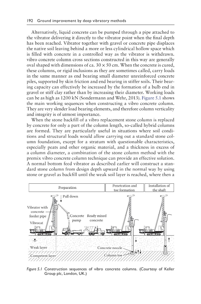
can be as high as 1200 kN (Sondermann and Wehr, 2013). Figure 5.1 shows
the main working sequences when constructing a vibro concrete column.
They are very slender load bearing elements, and therefore column verticality
and integrity is of utmost importance.
When the stone backfill of a vibro replacement stone column is replaced
by concrete for only a part of the column length, so-called hybrid columns
are formed. They are particularly useful in situations where soil conditions and structural loads would allow carrying out a standard stone column foundation, except for a stratum with questionable characteristics,
especially peats and other organic material, and a thickness in excess of
a column diameter, a combination of the stone column method with the
premix vibro concrete column technique can provide an effective solution.
A normal bottom feed vibrator as described earlier will construct a standard stone column from design depth upward in the normal way by using
stone or gravel as backfill until the weak soil layer is reached, where then a
Preparation
Penetration and
toe formation
Installation of
the shaft
Weak layer
Competent layer
Pull down
Vibrocat
Vibrator with
concrete
feeder pipe
Concrete
pump
Ready mixed
concrete
Concrete nozzle
Column toe
Figure 5.1 Construction sequences of vibro concrete columns. (Courtesy of Keller
Group plc, London, UK.)
Alternatively, liquid concrete can be pumped through a pipe attached to
the vibrator delivering it directly to the vibrator point when the final depth
has been reached. Vibrator together with gravel or concrete pipe displaces
the native soil leaving behind a more or less cylindrical hollow space which
is filled with concrete in a controlled way as the vibrator is withdrawn.
vibro concrete column cross sections constructed in this way are generally
oval shaped with dimensions of ca. 30 × 50 cm. When the concrete is cured,
these columns, or rigid inclusions as they are sometimes called, carry loads
in the same manner as end bearing small diameter unreinforced concrete
piles, supported by skin friction and end bearing in stiffer soils. Their bearing capacity can effectively be increased by the formation of a bulb end in
gravel or stiff clay rather than by increasing their diameter. Working loads
can be as high as 1200 kN (Sondermann and Wehr, 2013). Figure 5.1 shows
the main working sequences when constructing a vibro concrete column.
They are very slender load bearing elements, and therefore column verticality
and integrity is of utmost importance.
When the stone backfill of a vibro replacement stone column is replaced
by concrete for only a part of the column length, so-called hybrid columns
are formed. They are particularly useful in situations where soil conditions and structural loads would allow carrying out a standard stone column foundation, except for a stratum with questionable characteristics,
especially peats and other organic material, and a thickness in excess of
a column diameter, a combination of the stone column method with the
premix vibro concrete column technique can provide an effective solution.
A normal bottom feed vibrator as described earlier will construct a standard stone column from design depth upward in the normal way by using
stone or gravel as backfill until the weak soil layer is reached, where then a
Preparation
Penetration and
toe formation
Installation of
the shaft
Weak layer
Competent layer
Pull down
Vibrocat
Vibrator with
concrete
feeder pipe
Concrete
pump
Ready mixed
concrete
Concrete nozzle
Column toe
Figure 5.1 Construction sequences of vibro concrete columns. (Courtesy of Keller
Group plc, London, UK.)