

160 Ground improvement by deep vibratory methods
With the adjusted load ratio ′
m 1 , the average strength of the improved
ground can be calculated by the following equations:
ϕ
ϕ
ϕ
avg =
′′ ⋅
+ − ′′ ⋅
arctan(
tan
(
) tan )
m
m
c
s
1
1
1
(4.71)
c
m c s
avg = − ′′ ⋅
(
)
1
1
(4.72)
Calculating the average cohesion c avg also on the basis of the reduced load
ratio ′
m 1 is on the safe side, since physically one could apply the area ratio,
which would lead to higher cohesion values.
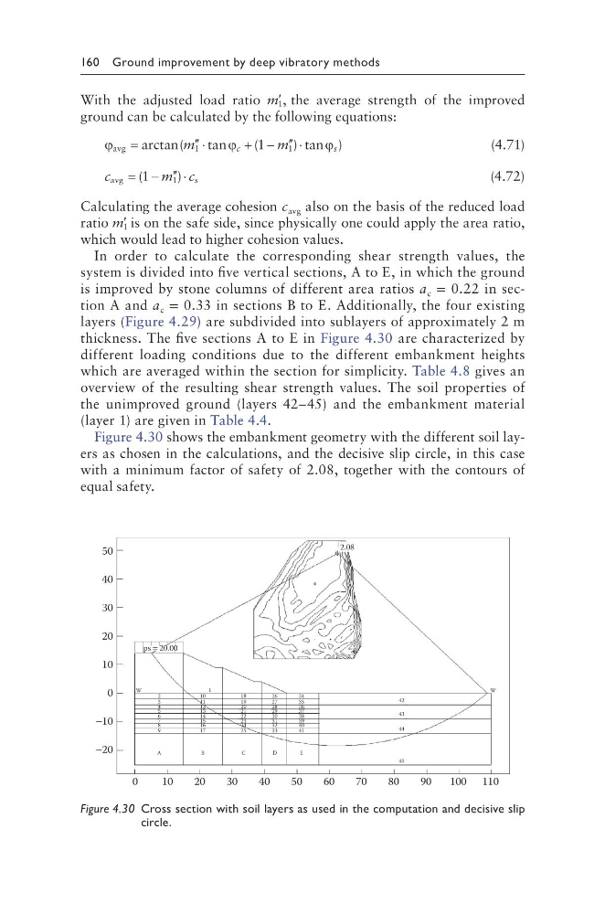
In order to calculate the corresponding shear strength values, the
system is divided into five vertical sections, A to E, in which the ground
is improved by stone columns of different area ratios a c = 0.22 in section A and a c = 0.33 in sections B to E. Additionally, the four existing
layers (Figure 4.29) are subdivided into sublayers of approximately 2 m
thickness. The five sections A to E in Figure 4.30 are characterized by
different loading conditions due to the different embankment heights
which are averaged within the section for simplicity. Table 4.8 gives an
overview of the resulting shear strength values. The soil properties of
the unimproved ground (layers 42–45) and the embankment material
(layer 1) are given in Table 4.4.
Figure 4.30 shows the embankment geometry with the different soil layers as chosen in the calculations, and the decisive slip circle, in this case
with a minimum factor of safety of 2.08, together with the contours of
equal safety.
50
40
30
20
10
0
−10
−20
0
10
20
30
40
50
60
70
80
90
100 110
ps = 20.00
2
3
4
5
6
7
8
9
10
1
11
12
13
14
15
16
17
18
19
20
21
22
23
24
25
26
27
28
29
30
31
32
33
34
35
36
37
38
39
40
41
A
B
C
D
E
45
2.08
W
42
43
44
W
Figure 4.30 Cross section with soil layers as used in the computation and decisive slip
circle.
With the adjusted load ratio ′
m 1 , the average strength of the improved
ground can be calculated by the following equations:
ϕ
ϕ
ϕ
avg =
′′ ⋅
+ − ′′ ⋅
arctan(
tan
(
) tan )
m
m
c
s
1
1
1
(4.71)
c
m c s
avg = − ′′ ⋅
(
)
1
1
(4.72)
Calculating the average cohesion c avg also on the basis of the reduced load
ratio ′
m 1 is on the safe side, since physically one could apply the area ratio,
which would lead to higher cohesion values.
In order to calculate the corresponding shear strength values, the
system is divided into five vertical sections, A to E, in which the ground
is improved by stone columns of different area ratios a c = 0.22 in section A and a c = 0.33 in sections B to E. Additionally, the four existing
layers (Figure 4.29) are subdivided into sublayers of approximately 2 m
thickness. The five sections A to E in Figure 4.30 are characterized by
different loading conditions due to the different embankment heights
which are averaged within the section for simplicity. Table 4.8 gives an
overview of the resulting shear strength values. The soil properties of
the unimproved ground (layers 42–45) and the embankment material
(layer 1) are given in Table 4.4.
Figure 4.30 shows the embankment geometry with the different soil layers as chosen in the calculations, and the decisive slip circle, in this case
with a minimum factor of safety of 2.08, together with the contours of
equal safety.
50
40
30
20
10
0
−10
−20
0
10
20
30
40
50
60
70
80
90
100 110
ps = 20.00
2
3
4
5
6
7
8
9
10
1
11
12
13
14
15
16
17
18
19
20
21
22
23
24
25
26
27
28
29
30
31
32
33
34
35
36
37
38
39
40
41
A
B
C
D
E
45
2.08
W
42
43
44
W
Figure 4.30 Cross section with soil layers as used in the computation and decisive slip
circle.