

142 Ground improvement by deep vibratory methods
T
k
t
m
d
ad
h
w
d
v3
/
=
⋅
⋅ ( )
γ
2
2
(4.45)
where:
k h is the horizontal permeability of the soil
γ w is the unit weight of water
t d is the duration time of earthquake
d is the diameter of drain
m v3 is the coefficient of volume compressibility
The above design assumes an infinite permeability for the stone column
material but it is also valid for stone column permeability in excess of
200·k h of the soil. In addition to the soil permeability k h , the computation
requires the following parameters, which needs to be determined specifically for each project:
200
100
50
25
10
5
2
0.0
0.8
0.6
0.4
0.2
1.0
0.4
0.5
0.6
0.3
0.2
0.1
0.0
0.0
0.8
0.6
0.4
0.2
1.0
0.4
0 .5
0.6
0.3
0.2
0.1
0.0
0.4
0.5
0.6
0.3
0.2
0.1
0.0
0.4
0 .5
0.6
0.3
0.2
0.1
0.0
100
25
10
5
2
0.0
0.8
0.6
0.4
0.2
1.0
0.0
0.8
0.6
0.4
0.2
1.0
= 1
= 2
= 3
= 4
200
50
2
2
100
25
10
5
200
50
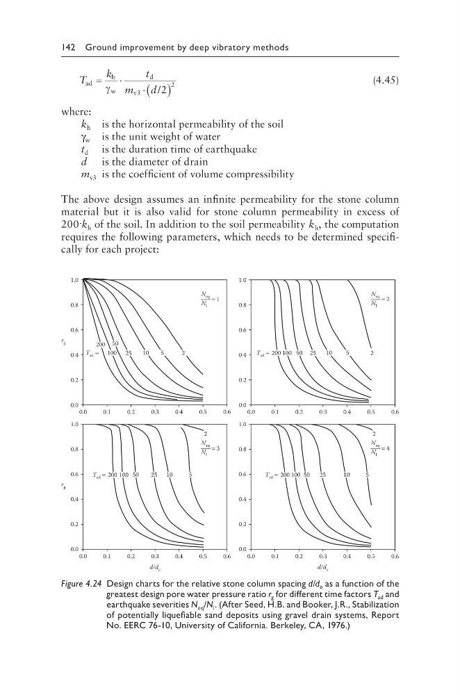
Figure 4.24 Design charts for the relative stone column spacing d/d e as a function of the
greatest design pore water pressure ratio r g for different time factors T ad and
earthquake severities N eq /N l . (After Seed, H.B. and Booker, J.R., Stabilization
of potentially liquefiable sand deposits using gravel drain systems, Report
No. EERC 76-10, University of California. Berkeley, CA, 1976.)
T
k
t
m
d
ad
h
w
d
v3
/
=
⋅
⋅ ( )
γ
2
2
(4.45)
where:
k h is the horizontal permeability of the soil
γ w is the unit weight of water
t d is the duration time of earthquake
d is the diameter of drain
m v3 is the coefficient of volume compressibility
The above design assumes an infinite permeability for the stone column
material but it is also valid for stone column permeability in excess of
200·k h of the soil. In addition to the soil permeability k h , the computation
requires the following parameters, which needs to be determined specifically for each project:
200
100
50
25
10
5
2
0.0
0.8
0.6
0.4
0.2
1.0
0.4
0.5
0.6
0.3
0.2
0.1
0.0
0.0
0.8
0.6
0.4
0.2
1.0
0.4
0 .5
0.6
0.3
0.2
0.1
0.0
0.4
0.5
0.6
0.3
0.2
0.1
0.0
0.4
0 .5
0.6
0.3
0.2
0.1
0.0
100
25
10
5
2
0.0
0.8
0.6
0.4
0.2
1.0
0.0
0.8
0.6
0.4
0.2
1.0
= 1
= 2
= 3
= 4
200
50
2
2
100
25
10
5
200
50
Figure 4.24 Design charts for the relative stone column spacing d/d e as a function of the
greatest design pore water pressure ratio r g for different time factors T ad and
earthquake severities N eq /N l . (After Seed, H.B. and Booker, J.R., Stabilization
of potentially liquefiable sand deposits using gravel drain systems, Report
No. EERC 76-10, University of California. Berkeley, CA, 1976.)