

140 Ground improvement by deep vibratory methods
loads are generally transferred by friction from the load distribution layer
placed below the foundation into the heads of the stone columns. When
considering only the shear capacity of the stone column, that is, neglecting
the higher shear resistance of stone column and tributary soil, a safety factor against earthquake-induced shear failure can be defined for the infinite
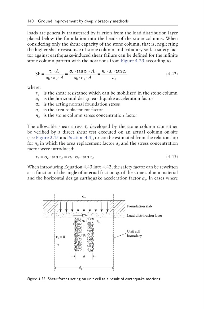
stone column pattern with the notations from Figure 4.23 according to
SF
c
c
h
v
c
c
c
h
c
c
c
h
v
=
⋅
⋅ ⋅
=
⋅
⋅
⋅ ⋅
=
⋅ ⋅
τ
σ
σ
ϕ
σ
ϕ
A
a
A
A
a
A
n a
a
tan
t an
(4.42)
where:
τ c is the shear resistance which can be mobilized in the stone column
a h is the horizontal design earthquake acceleration factor
σ v is the acting normal foundation stress
a c is the area replacement factor
n c is the stone column stress concentration factor
The allowable shear stress τ c developed by the stone column can either
be verified by a direct shear test executed on an actual column on-site
(see Figure 2.15 and Section 4.4), or can be estimated from the relationship
for n c in which the area replacement factor a c and the stress concentration
factor were introduced:
τ σ
ϕ
σ
ϕ
c
c
c
c
v
c
= ⋅
= ⋅ ⋅
tan
t an
n
(4.43)
When introducing Equation 4.43 into 4.42, the safety factor can be rewritten
as a function of the angle of internal friction φ c of the stone column material
and the horizontal design earthquake acceleration factor a h . In cases where
Foundation slab
Unit cell
boundary
Load distribution layer
d
d e
c s
φ s = 0
φ c
τ c
σ v
Figure 4.23 Shear forces acting on unit cell as a result of earthquake motions.
loads are generally transferred by friction from the load distribution layer
placed below the foundation into the heads of the stone columns. When
considering only the shear capacity of the stone column, that is, neglecting
the higher shear resistance of stone column and tributary soil, a safety factor against earthquake-induced shear failure can be defined for the infinite
stone column pattern with the notations from Figure 4.23 according to
SF
c
c
h
v
c
c
c
h
c
c
c
h
v
=
⋅
⋅ ⋅
=
⋅
⋅
⋅ ⋅
=
⋅ ⋅
τ
σ
σ
ϕ
σ
ϕ
A
a
A
A
a
A
n a
a
tan
t an
(4.42)
where:
τ c is the shear resistance which can be mobilized in the stone column
a h is the horizontal design earthquake acceleration factor
σ v is the acting normal foundation stress
a c is the area replacement factor
n c is the stone column stress concentration factor
The allowable shear stress τ c developed by the stone column can either
be verified by a direct shear test executed on an actual column on-site
(see Figure 2.15 and Section 4.4), or can be estimated from the relationship
for n c in which the area replacement factor a c and the stress concentration
factor were introduced:
τ σ
ϕ
σ
ϕ
c
c
c
c
v
c
= ⋅
= ⋅ ⋅
tan
t an
n
(4.43)
When introducing Equation 4.43 into 4.42, the safety factor can be rewritten
as a function of the angle of internal friction φ c of the stone column material
and the horizontal design earthquake acceleration factor a h . In cases where
Foundation slab
Unit cell
boundary
Load distribution layer
d
d e
c s
φ s = 0
φ c
τ c
σ v
Figure 4.23 Shear forces acting on unit cell as a result of earthquake motions.