

displacement experiment. In such experiment, the dissociation of
the complex is turned into an essentially irreversible reaction by
trapping one of the interacting proteins with an alternative protein
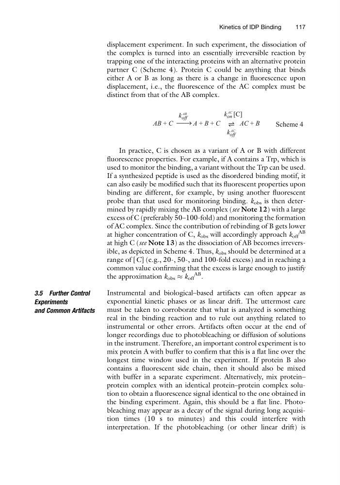
partner C (Scheme 4). Protein C could be anything that binds
either A or B as long as there is a change in fluorescence upon
displacement, i.e., the fluorescence of the AC complex must be
distinct from that of the AB complex.
AB + C
A + B + C
AC + B
k on [C]
k off
k off
AC
Scheme 4
AB
AC
In practice, C is chosen as a variant of A or B with different
fluorescence properties. For example, if A contains a Trp, which is
used to monitor the binding, a variant without the Trp can be used.
If a synthesized peptide is used as the disordered binding motif, it
can also easily be modified such that its fluorescent properties upon
binding are different, for example, by using another fluorescent
probe than that used for monitoring binding. k obs is then determined by rapidly mixing the AB complex (see Note 12) with a large
excess of C (preferably 50–100-fold) and monitoring the formation
of AC complex. Since the contribution of rebinding of B gets lower
at higher concentration of C, k obs will accordingly approach k off
AB
at high C (see Note 13) as the dissociation of AB becomes irreversible, as depicted in Scheme 4. Thus, k obs should be determined at a
range of [C] (e.g., 20-, 50-, and 100-fold excess) and in reaching a
common value confirming that the excess is large enough to justify
the approximation k obs % k off
AB
.
3.5 Further Control
Experiments
and Common Artifacts
Instrumental and biological–based artifacts can often appear as
exponential kinetic phases or as linear drift. The uttermost care
must be taken to corroborate that what is analyzed is something
real in the binding reaction and to rule out anything related to
instrumental or other errors. Artifacts often occur at the end of
longer recordings due to photobleaching or diffusion of solutions
in the instrument. Therefore, an important control experiment is to
mix protein A with buffer to confirm that this is a flat line over the
longest time window used in the experiment. If protein B also
contains a fluorescent side chain, then it should also be mixed
with buffer in a separate experiment. Alternatively, mix protein–
protein complex with an identical protein–protein complex solution to obtain a fluorescence signal identical to the one obtained in
the binding experiment. Again, this should be a flat line. Photobleaching may appear as a decay of the signal during long acquisition times (10 s to minutes) and this could interfere with
interpretation. If the photobleaching (or other linear drift) is
Kinetics of IDP Binding
117
the complex is turned into an essentially irreversible reaction by
trapping one of the interacting proteins with an alternative protein
partner C (Scheme 4). Protein C could be anything that binds
either A or B as long as there is a change in fluorescence upon
displacement, i.e., the fluorescence of the AC complex must be
distinct from that of the AB complex.
AB + C
A + B + C
AC + B
k on [C]
k off
k off
AC
Scheme 4
AB
AC
In practice, C is chosen as a variant of A or B with different
fluorescence properties. For example, if A contains a Trp, which is
used to monitor the binding, a variant without the Trp can be used.
If a synthesized peptide is used as the disordered binding motif, it
can also easily be modified such that its fluorescent properties upon
binding are different, for example, by using another fluorescent
probe than that used for monitoring binding. k obs is then determined by rapidly mixing the AB complex (see Note 12) with a large
excess of C (preferably 50–100-fold) and monitoring the formation
of AC complex. Since the contribution of rebinding of B gets lower
at higher concentration of C, k obs will accordingly approach k off
AB
at high C (see Note 13) as the dissociation of AB becomes irreversible, as depicted in Scheme 4. Thus, k obs should be determined at a
range of [C] (e.g., 20-, 50-, and 100-fold excess) and in reaching a
common value confirming that the excess is large enough to justify
the approximation k obs % k off
AB
.
3.5 Further Control
Experiments
and Common Artifacts
Instrumental and biological–based artifacts can often appear as
exponential kinetic phases or as linear drift. The uttermost care
must be taken to corroborate that what is analyzed is something
real in the binding reaction and to rule out anything related to
instrumental or other errors. Artifacts often occur at the end of
longer recordings due to photobleaching or diffusion of solutions
in the instrument. Therefore, an important control experiment is to
mix protein A with buffer to confirm that this is a flat line over the
longest time window used in the experiment. If protein B also
contains a fluorescent side chain, then it should also be mixed
with buffer in a separate experiment. Alternatively, mix protein–
protein complex with an identical protein–protein complex solution to obtain a fluorescence signal identical to the one obtained in
the binding experiment. Again, this should be a flat line. Photobleaching may appear as a decay of the signal during long acquisition times (10 s to minutes) and this could interfere with
interpretation. If the photobleaching (or other linear drift) is
Kinetics of IDP Binding
117