

user training. These steps are presented in detail below.
The designing, sizing, and the installation are very
critical steps. When a system is wrongly designed,
sized, or installed, it will not perform optimally. A
number of sizing methods exist and have been tried and
they work. However, most of them are expensive, complicated, and require great understanding of computer
modeling (Majid Alabdul Salam et al., 2013), simulation (M. Chikh, Mahrane, & Bouachri, 2011; Mohit
Jain, & Neha Tiwari, 2012; N.D. Kaushika, Nalin, &
Nalin, 2005), and even programming (M. Sidrach-deCardona & Ll. Mora Lopez, 1998). In many developing countries, the sales person is both the installer
and also the PV solar system sizer, although most
have very limited knowledge in the area of solar photovoltaic (PV) sizing and installation. The tendency
is therefore to use unjustified estimates which more
often than not do not meet the clients’ need. A simple
straight-forward method is needed for the individual
with basic education and who wants to do professional PV sizing, especially in the rural developing
world.
In this work, we present and compare by way of an
example, two simple sizing methods which can easily
be adopted by the PV professional with basic education
and limited computer knowledge and skill. We designate the first method as the charging current method
(CCM) and the second method as the energy output
method (EOM), but first we describe some key steps
common to both methods.
2 METHODOLOGY
2.1 Common steps in both methods
2.1.1 Visit the site of installation
A site visit is always necessary before any work on
system design and sizing begins.The site visit helps the
installer to: have a real assessment of the solar resource
in the area, create an impression of how and where the
system will be installed, assess any impediments to
the system working properly and optimally like nearby
trees that can cause shading, type of roof thatching
which determines how the panels will be mounted, area
terrain which determines the means to the place, and
assess the risk and hazards involved in the work etc.
Table 1. Details of the load demand and how to arrange the columns for calculation purposes.
Column 1
Column 2
Column 3
Column 4
Column 5
Column 6
Column 7
Room
No of
System
Appliance
Daily
Total
Daily
Appliances
Voltage
Power
usage
Power
energy
(V)
Rating
(hrs)
(W)
Demand
(W)
(Whrs)
1
2
3
4
2.1.2 Determine the solar resource in Peak Sun
Hours (PSH)
The amount of irradiance in the area determines how
much energy the modules can generate. The solar
resource available in the area is therefore very necessary. We can get this from either the nearest meteorological station, or one can do actual site measurements
if the right equipment is available—irradiance meter or
pyranometer (but this may take some time)—or even
get it from reliable internet resource maps. If the irradiance is given in W/m
2 /day or kW/m
2 /yr, then we have
to calculate the value per day by dividing by the number of days in a year. In sizing calculation, we use PSH
(how many hours we would have the same energy if the
irradiance was the standard 1000 W/m
2 (1 kW/m
2 )).
The irradiance per day then needs to be divided by the
standard value solar irradiance on the earth’s surface,
1000 W/m
2 or 1 kW/m
2 to get PSH.
2.1.3 Compute the Daily Energy Demand (DED)
Next we need to determine the daily energy required
by the user. We do this by talking to the user about
their needs and future plans so we can factor that into
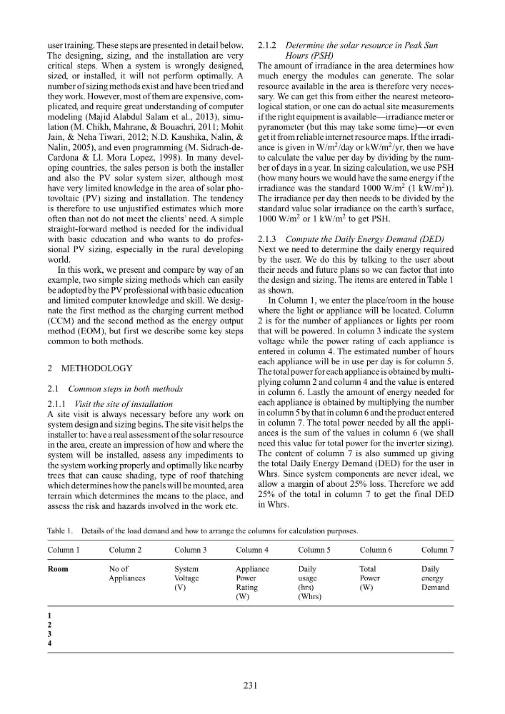
the design and sizing. The items are entered in Table 1
as shown.
In Column 1, we enter the place/room in the house
where the light or appliance will be located. Column
2 is for the number of appliances or lights per room
that will be powered. In column 3 indicate the system
voltage while the power rating of each appliance is
entered in column 4. The estimated number of hours
each appliance will be in use per day is for column 5.
The total power for each appliance is obtained by multiplying column 2 and column 4 and the value is entered
in column 6. Lastly the amount of energy needed for
each appliance is obtained by multiplying the number
in column 5 by that in column 6 and the product entered
in column 7. The total power needed by all the appliances is the sum of the values in column 6 (we shall
need this value for total power for the inverter sizing).
The content of column 7 is also summed up giving
the total Daily Energy Demand (DED) for the user in
Whrs. Since system components are never ideal, we
allow a margin of about 25% loss. Therefore we add
25% of the total in column 7 to get the final DED
in Whrs.
231
The designing, sizing, and the installation are very
critical steps. When a system is wrongly designed,
sized, or installed, it will not perform optimally. A
number of sizing methods exist and have been tried and
they work. However, most of them are expensive, complicated, and require great understanding of computer
modeling (Majid Alabdul Salam et al., 2013), simulation (M. Chikh, Mahrane, & Bouachri, 2011; Mohit
Jain, & Neha Tiwari, 2012; N.D. Kaushika, Nalin, &
Nalin, 2005), and even programming (M. Sidrach-deCardona & Ll. Mora Lopez, 1998). In many developing countries, the sales person is both the installer
and also the PV solar system sizer, although most
have very limited knowledge in the area of solar photovoltaic (PV) sizing and installation. The tendency
is therefore to use unjustified estimates which more
often than not do not meet the clients’ need. A simple
straight-forward method is needed for the individual
with basic education and who wants to do professional PV sizing, especially in the rural developing
world.
In this work, we present and compare by way of an
example, two simple sizing methods which can easily
be adopted by the PV professional with basic education
and limited computer knowledge and skill. We designate the first method as the charging current method
(CCM) and the second method as the energy output
method (EOM), but first we describe some key steps
common to both methods.
2 METHODOLOGY
2.1 Common steps in both methods
2.1.1 Visit the site of installation
A site visit is always necessary before any work on
system design and sizing begins.The site visit helps the
installer to: have a real assessment of the solar resource
in the area, create an impression of how and where the
system will be installed, assess any impediments to
the system working properly and optimally like nearby
trees that can cause shading, type of roof thatching
which determines how the panels will be mounted, area
terrain which determines the means to the place, and
assess the risk and hazards involved in the work etc.
Table 1. Details of the load demand and how to arrange the columns for calculation purposes.
Column 1
Column 2
Column 3
Column 4
Column 5
Column 6
Column 7
Room
No of
System
Appliance
Daily
Total
Daily
Appliances
Voltage
Power
usage
Power
energy
(V)
Rating
(hrs)
(W)
Demand
(W)
(Whrs)
1
2
3
4
2.1.2 Determine the solar resource in Peak Sun
Hours (PSH)
The amount of irradiance in the area determines how
much energy the modules can generate. The solar
resource available in the area is therefore very necessary. We can get this from either the nearest meteorological station, or one can do actual site measurements
if the right equipment is available—irradiance meter or
pyranometer (but this may take some time)—or even
get it from reliable internet resource maps. If the irradiance is given in W/m
2 /day or kW/m
2 /yr, then we have
to calculate the value per day by dividing by the number of days in a year. In sizing calculation, we use PSH
(how many hours we would have the same energy if the
irradiance was the standard 1000 W/m
2 (1 kW/m
2 )).
The irradiance per day then needs to be divided by the
standard value solar irradiance on the earth’s surface,
1000 W/m
2 or 1 kW/m
2 to get PSH.
2.1.3 Compute the Daily Energy Demand (DED)
Next we need to determine the daily energy required
by the user. We do this by talking to the user about
their needs and future plans so we can factor that into
the design and sizing. The items are entered in Table 1
as shown.
In Column 1, we enter the place/room in the house
where the light or appliance will be located. Column
2 is for the number of appliances or lights per room
that will be powered. In column 3 indicate the system
voltage while the power rating of each appliance is
entered in column 4. The estimated number of hours
each appliance will be in use per day is for column 5.
The total power for each appliance is obtained by multiplying column 2 and column 4 and the value is entered
in column 6. Lastly the amount of energy needed for
each appliance is obtained by multiplying the number
in column 5 by that in column 6 and the product entered
in column 7. The total power needed by all the appliances is the sum of the values in column 6 (we shall
need this value for total power for the inverter sizing).
The content of column 7 is also summed up giving
the total Daily Energy Demand (DED) for the user in
Whrs. Since system components are never ideal, we
allow a margin of about 25% loss. Therefore we add
25% of the total in column 7 to get the final DED
in Whrs.
231