

358
CHAPTER 7. LABORATORY WAVE GENERATION
First-Order Variable-Draft Flap-Type Wavemaker Solution
H
'So
4 sinh kh
sinh 2kh + 2kh
• i ».
(cosh kl — cosh kh)
sinh kh 4--------- —---- - ------ -
k(h — I)
(7.91)
For the special case when I — 0, Eqn. 7.91 reverts to the equation for a
flap-type wavemaker hinged at the bottom (Eqn. 7.59).
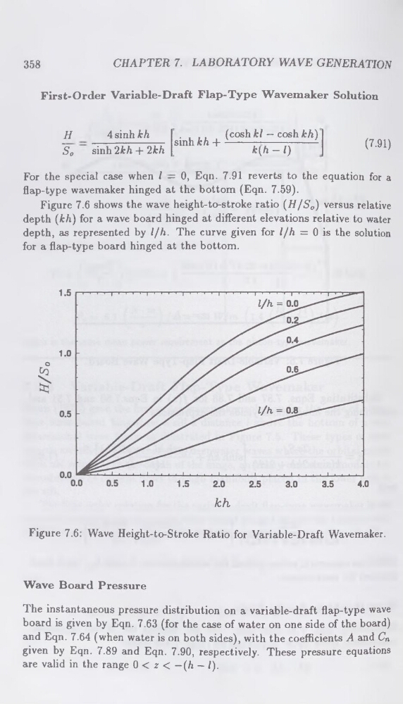
Figure 7.6 shows the wave height-to-stroke ratio (H/So) versus relative
depth (kh) for a wave board hinged at different elevations relative to water
depth, as represented by l/h. The curve given for l/h = 0 is the solution
for a flap-type board hinged at the bottom.
Figure 7.6: Wave Height-to-Stroke Ratio for Variable-Draft Wavemaker.
Wave Board Pressure
The instantaneous pressure distribution on a variable-draft flap-type wave
board is given by Eqn. 7.63 (for the case of water on one side of the board)
and Eqn. 7.64 (when water is on both sides), with the coefficients A and Cn
given by Eqn. 7.89 and Eqn. 7.90, respectively. These pressure equations
are valid in the range 0 < z < — (h — I).
CHAPTER 7. LABORATORY WAVE GENERATION
First-Order Variable-Draft Flap-Type Wavemaker Solution
H
'So
4 sinh kh
sinh 2kh + 2kh
• i ».
(cosh kl — cosh kh)
sinh kh 4--------- —---- - ------ -
k(h — I)
(7.91)
For the special case when I — 0, Eqn. 7.91 reverts to the equation for a
flap-type wavemaker hinged at the bottom (Eqn. 7.59).
Figure 7.6 shows the wave height-to-stroke ratio (H/So) versus relative
depth (kh) for a wave board hinged at different elevations relative to water
depth, as represented by l/h. The curve given for l/h = 0 is the solution
for a flap-type board hinged at the bottom.
Figure 7.6: Wave Height-to-Stroke Ratio for Variable-Draft Wavemaker.
Wave Board Pressure
The instantaneous pressure distribution on a variable-draft flap-type wave
board is given by Eqn. 7.63 (for the case of water on one side of the board)
and Eqn. 7.64 (when water is on both sides), with the coefficients A and Cn
given by Eqn. 7.89 and Eqn. 7.90, respectively. These pressure equations
are valid in the range 0 < z < — (h — I).