

5.4. VERTICAL-WALL STRUCTURES
219
Compression Shock. If waves approaching a vertical-wall structure are
concave in shape, as shown in the middle illustration of Figure 5.7, air can
be trapped between the wall and the wave. This produces a compression
shock which is very complex, and Hudson, et al. (1979) stated that only the
impulse portion of the response can be scaled to prototype using Froude
scaling (Eqn. 5.50).
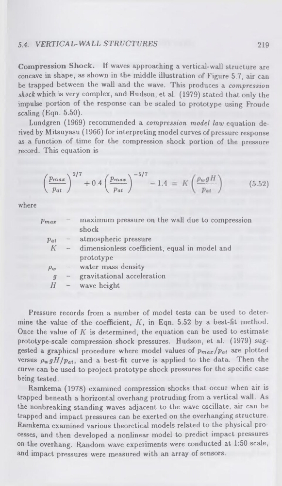
Lundgren (1969) recommended a compression model law equation derived by Mitsuyasu (1966) for interpreting model curves of pressure response
as a function of time for the compression shock portion of the pressure
record. This equation is
2/7
\“5/7
+ 0.4(^)
\ Pat J
1.4
(5.52)
where
Pmax ~ maximum pressure on the wall due to compression
shock
pat - atmospheric pressure
K - dimensionless coefficient, equal in model and
prototype
pw - water mass density
g - gravitational acceleration
H - wave height
Pressure records from a number of model tests can be used to determine the value of the coefficient, K, in Eqn. 5.52 by a best-fit method.
Once the value of K is determined, the equation can be used to estimate
prototype-scale compression shock pressures. Hudson, et al. (1979) suggested a graphical procedure where model values of pmax/Pat are plotted
versus pwgH/pat, and a best-fit curve is applied to the data. Then the
curve can be used to project prototype shock pressures for the specific case
being tested.
Ramkema (1978) examined compression shocks that occur when air is
trapped beneath a horizontal overhang protruding from a vertical wall. As
the nonbreaking standing waves adjacent to the wave oscillate, air can be
trapped and impact pressures can be exerted on the overhanging structure.
Ramkema examined various theoretical models related to the physical processes, and then developed a nonlinear model to predict impact pressures
on the overhang. Random wave experiments were conducted at 1:50 scale,
and impact pressures were measured with an array of sensors.
219
Compression Shock. If waves approaching a vertical-wall structure are
concave in shape, as shown in the middle illustration of Figure 5.7, air can
be trapped between the wall and the wave. This produces a compression
shock which is very complex, and Hudson, et al. (1979) stated that only the
impulse portion of the response can be scaled to prototype using Froude
scaling (Eqn. 5.50).
Lundgren (1969) recommended a compression model law equation derived by Mitsuyasu (1966) for interpreting model curves of pressure response
as a function of time for the compression shock portion of the pressure
record. This equation is
2/7
\“5/7
+ 0.4(^)
\ Pat J
1.4
(5.52)
where
Pmax ~ maximum pressure on the wall due to compression
shock
pat - atmospheric pressure
K - dimensionless coefficient, equal in model and
prototype
pw - water mass density
g - gravitational acceleration
H - wave height
Pressure records from a number of model tests can be used to determine the value of the coefficient, K, in Eqn. 5.52 by a best-fit method.
Once the value of K is determined, the equation can be used to estimate
prototype-scale compression shock pressures. Hudson, et al. (1979) suggested a graphical procedure where model values of pmax/Pat are plotted
versus pwgH/pat, and a best-fit curve is applied to the data. Then the
curve can be used to project prototype shock pressures for the specific case
being tested.
Ramkema (1978) examined compression shocks that occur when air is
trapped beneath a horizontal overhang protruding from a vertical wall. As
the nonbreaking standing waves adjacent to the wave oscillate, air can be
trapped and impact pressures can be exerted on the overhanging structure.
Ramkema examined various theoretical models related to the physical processes, and then developed a nonlinear model to predict impact pressures
on the overhang. Random wave experiments were conducted at 1:50 scale,
and impact pressures were measured with an array of sensors.