

5.3. SLOPING IMPERMEABLE STRUCTURES
213
for the case of NPa = 1. These moment and torque scales apply only to
stresses caused by static or pulsating loads.
Burcharth, et al. (1991) pointed out that insertion of the load cell into
the model armor unit changes the material properties so impact-induced
shock waves will not propagate the same as in the solid prototype units.
Therefore, impacts stresses measured by the load cell cannot be directly
related to the prototype through a theoretical scale factor. However, an
empirical impact stress scale factor for a specific load cell can be determined using a calibration method described by Burcharth, et al. (1991).
Comparison of results from controlled impact tests performed on large-scale
concrete armor units and small-scale “load-cell” units allows estimation of
an apparent elastic modulus for the instrumented unit that can be used in
Eqn. 5.45 to determine the impact stress scale.
5.3 Sloping Impermeable Structures
5.3.1 Sloping Impermeable Structure Scaling
Non-permeable sloping structures dissipate incident wave energy through
wave breaking on the slope and subsequent wave runup on the structure.
Waves can break on smooth slopes in the form of plunging breakers, which
produce high impact pressures that are a critical design factor for the
structure. Sloping impermeable structures have slopes between 1:2 and
1:6 (Oumeraci 1984), and they are scaled as undistorted geometric models
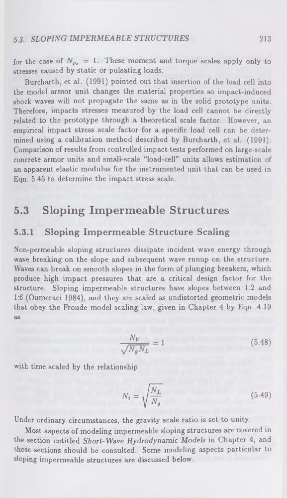
that obey the Froude model scaling law, given in Chapter 4 by Eqn. 4.19
as
Nv
(5.48)
with time scaled by the relationship
(5.49)
Under ordinary circumstances, the gravity scale ratio is set to unity.
Most aspects of modeling impermeable sloping structures are covered in
the section entitled Short-Wave Hydrodynamic Models in Chapter 4, and
those sections should be consulted. Some modeling aspects particular to
sloping impermeable structures are discussed below.
213
for the case of NPa = 1. These moment and torque scales apply only to
stresses caused by static or pulsating loads.
Burcharth, et al. (1991) pointed out that insertion of the load cell into
the model armor unit changes the material properties so impact-induced
shock waves will not propagate the same as in the solid prototype units.
Therefore, impacts stresses measured by the load cell cannot be directly
related to the prototype through a theoretical scale factor. However, an
empirical impact stress scale factor for a specific load cell can be determined using a calibration method described by Burcharth, et al. (1991).
Comparison of results from controlled impact tests performed on large-scale
concrete armor units and small-scale “load-cell” units allows estimation of
an apparent elastic modulus for the instrumented unit that can be used in
Eqn. 5.45 to determine the impact stress scale.
5.3 Sloping Impermeable Structures
5.3.1 Sloping Impermeable Structure Scaling
Non-permeable sloping structures dissipate incident wave energy through
wave breaking on the slope and subsequent wave runup on the structure.
Waves can break on smooth slopes in the form of plunging breakers, which
produce high impact pressures that are a critical design factor for the
structure. Sloping impermeable structures have slopes between 1:2 and
1:6 (Oumeraci 1984), and they are scaled as undistorted geometric models
that obey the Froude model scaling law, given in Chapter 4 by Eqn. 4.19
as
Nv
(5.48)
with time scaled by the relationship
(5.49)
Under ordinary circumstances, the gravity scale ratio is set to unity.
Most aspects of modeling impermeable sloping structures are covered in
the section entitled Short-Wave Hydrodynamic Models in Chapter 4, and
those sections should be consulted. Some modeling aspects particular to
sloping impermeable structures are discussed below.