

5.2. RUBBLE-MOUND STRUCTURES
201
identifying those armor units that have moved. A common technique is
to construct the model structure with different colored (painted) armor
units placed in patterns. Some dislodged units will move into a region of a
different color and be easily recognized. The movement can be observed and
noted, or more conveniently, video and photographic documentation can
be used to record test results. Owen and Allsop (1983) described precision
photography to quantify armor displacement.
Quantifying damage by volumetric change requires that pre-test and
post-test profiles of the armor slope be measured in a consistent manner
for comparison. The test section should be surveyed over a set grid with
sufficient resolution to determine profile change with reasonable accuracy.
Spacing of soundings along the profile, and the number of profiles across the
test section (2-d test) varies widely between tests reported in the literature.
A “damage percentage” can be defined in a number of different ways.
For example, Hudson (1959) defined damage as the percentage of dislodged
armor units to the total number of armor units. Shimada, et al. (1986)
defined damage percentage as the ratio of armor units moved a length
greater than the armor unit height to the total number of units exposed to
wave action. T0rum, et al. (1979) defined damage as the reduction in the
average post-test armor layer thickness relative to the original undamaged
average armor layer thickness.
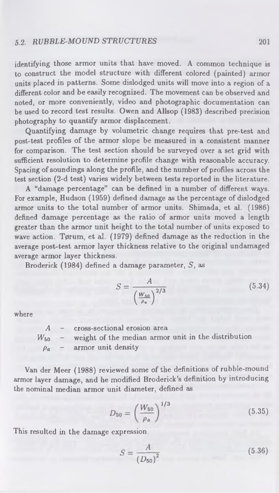
Broderick (1984) defined a damage parameter, S, as
(5.34)
where
A - cross-sectional erosion area
kFso ~ weight of the median armor unit in the distribution
pa - armor unit density
Van der Meer (1988) reviewed some of the definitions of rubble-mound
armor layer damage, and he modified Broderick’s definition by introducing
the nominal median armor unit diameter, defined as
1/3
(5.35)
This resulted in the damage expression
(^5o)2
(5.36)
201
identifying those armor units that have moved. A common technique is
to construct the model structure with different colored (painted) armor
units placed in patterns. Some dislodged units will move into a region of a
different color and be easily recognized. The movement can be observed and
noted, or more conveniently, video and photographic documentation can
be used to record test results. Owen and Allsop (1983) described precision
photography to quantify armor displacement.
Quantifying damage by volumetric change requires that pre-test and
post-test profiles of the armor slope be measured in a consistent manner
for comparison. The test section should be surveyed over a set grid with
sufficient resolution to determine profile change with reasonable accuracy.
Spacing of soundings along the profile, and the number of profiles across the
test section (2-d test) varies widely between tests reported in the literature.
A “damage percentage” can be defined in a number of different ways.
For example, Hudson (1959) defined damage as the percentage of dislodged
armor units to the total number of armor units. Shimada, et al. (1986)
defined damage percentage as the ratio of armor units moved a length
greater than the armor unit height to the total number of units exposed to
wave action. T0rum, et al. (1979) defined damage as the reduction in the
average post-test armor layer thickness relative to the original undamaged
average armor layer thickness.
Broderick (1984) defined a damage parameter, S, as
(5.34)
where
A - cross-sectional erosion area
kFso ~ weight of the median armor unit in the distribution
pa - armor unit density
Van der Meer (1988) reviewed some of the definitions of rubble-mound
armor layer damage, and he modified Broderick’s definition by introducing
the nominal median armor unit diameter, defined as
1/3
(5.35)
This resulted in the damage expression
(^5o)2
(5.36)