

96
CHAPTER 4. HYDRODYNAMIC MODELS
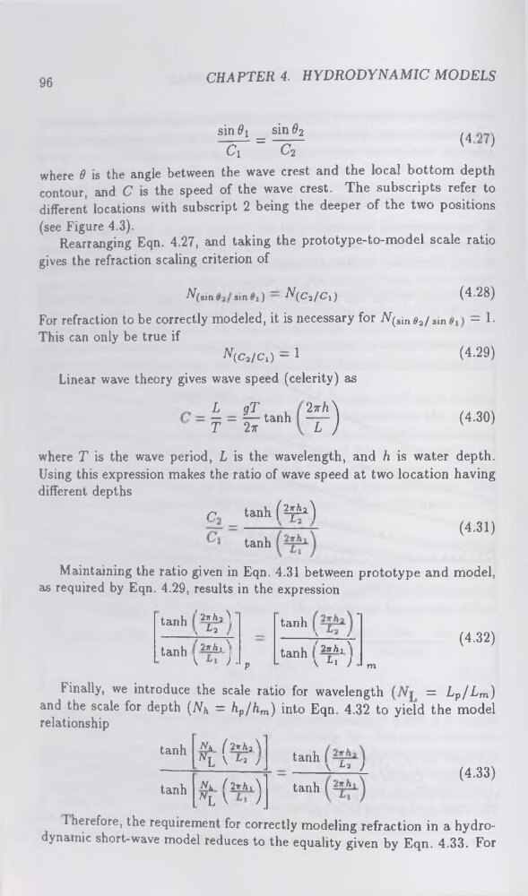
sin^! _ sin 02
/4
G " C2
{
}
where 0 is the angle between the wave crest and the local bottom depth
contour, and C is the speed of the wave crest. The subscripts refer to
different locations with subscript 2 being the deeper of the two positions
(see Figure 4.3).
Rearranging Eqn. 4.27, and taking the prototype-to-model scale ratio
gives the refraction scaling criterion of
N(sin
sin )
•^(C’2/<7i)
(4.28)
For refraction to be correctly modeled, it is necessary for ./V(sin 02/sin
— 1This can only be true if
^(c2/C!) - 1
(4.29)
Linear wave theory gives wave speed (celerity) as
L
gT
,
— — — tanh
T
27T
2irh \
~L~ J
(4.30)
where T is the wave period, L is the wavelength, and h is water depth.
Using this expression makes the ratio of wave speed at two location having
different depths
C
tanhf^2)
tanh
(4.31)
Maintaining the ratio given in Eqn. 4.31 between prototype and model,
as required by Eqn. 4.29, results in the expression
tanh
'27rh2^
< ^2 >
tanh
k
>
•
tanh
' 2irhx '
k
J - p
tanh
' 2-ïïhx '
\ Li ) m
(4.32)
Finally, we introduce the scale ratio for wavelength
= Lp/Lm)
and the scale for depth (AT& = hp/hm) into Eqn. 4.32 to yield the model
relationship
tanh
Nh ( 2tt/i2\
nL k L* /
tanh \ ^2 )
tanh Nh ( 2irA, \
"L V
<
tanh
I herefore, the requirement for correctly modeling refraction in a hydrodynamic short-wave model reduces to the equality given by Eqn. 4.33. For
(4.33)
CHAPTER 4. HYDRODYNAMIC MODELS
sin^! _ sin 02
/4
G " C2
{
}
where 0 is the angle between the wave crest and the local bottom depth
contour, and C is the speed of the wave crest. The subscripts refer to
different locations with subscript 2 being the deeper of the two positions
(see Figure 4.3).
Rearranging Eqn. 4.27, and taking the prototype-to-model scale ratio
gives the refraction scaling criterion of
N(sin
sin )
•^(C’2/<7i)
(4.28)
For refraction to be correctly modeled, it is necessary for ./V(sin 02/sin
— 1This can only be true if
^(c2/C!) - 1
(4.29)
Linear wave theory gives wave speed (celerity) as
L
gT
,
— — — tanh
T
27T
2irh \
~L~ J
(4.30)
where T is the wave period, L is the wavelength, and h is water depth.
Using this expression makes the ratio of wave speed at two location having
different depths
C
tanhf^2)
tanh
(4.31)
Maintaining the ratio given in Eqn. 4.31 between prototype and model,
as required by Eqn. 4.29, results in the expression
tanh
'27rh2^
< ^2 >
tanh
k
>
•
tanh
' 2irhx '
k
J - p
tanh
' 2-ïïhx '
\ Li ) m
(4.32)
Finally, we introduce the scale ratio for wavelength
= Lp/Lm)
and the scale for depth (AT& = hp/hm) into Eqn. 4.32 to yield the model
relationship
tanh
Nh ( 2tt/i2\
nL k L* /
tanh \ ^2 )
tanh Nh ( 2irA, \
"L V
<
tanh
I herefore, the requirement for correctly modeling refraction in a hydrodynamic short-wave model reduces to the equality given by Eqn. 4.33. For
(4.33)