

8. Design of Coastal Structures
265
structure, cargo handling equipment, and from imposed loading on the
deck slab, Compressive and uplift forces induced by overturning movements
due to loads 1 to 5 above and in some parts of the world piles may also
hâve to carry vertical and latéral loads from floating ice, and loading from
earthquakes.
It is possible that the combination of above forces may occur whereas
the cumulative of ail the forces may not happen. Hence, the design can be
carried over by considering the combination of forces as well. For instance,
the wind, wave, and current forces can occur simultaneously and in the same
direction, the forces due to berthing impact and mooring rope pull occur
in opposite directions. Taking the case of a vertical pile acting as a simple
cantilever from the point of Virtual fixity below the sea bed, and receiving a
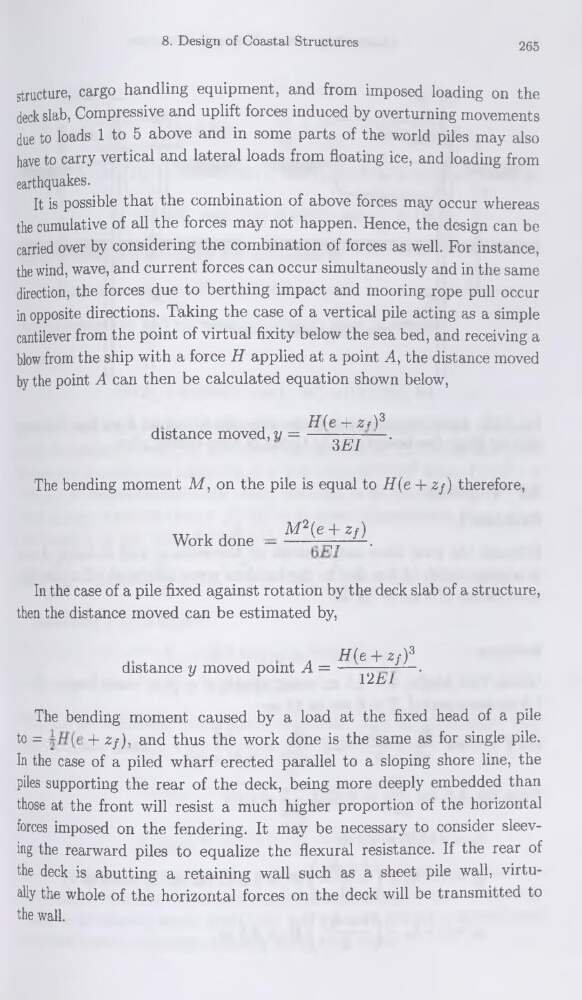
blow from the ship with a force H applied at a point A, the distance moved
by the point A can then be calculated équation shown below,
,
H(e-\-zA3
distance moved,?/ =---- Q
.
oEI
The bending moment M, on the pile is equal to H(e + zf) therefore,
xv i j
M2(e + zy)
Work done —-----__,T ■ .
In the case of a pile fixed against rotation by the deck slab of a structure,
then the distance moved can be estimated by,
.
W + */)3
distance y moved point A = —
—.
I2E1
The bending moment caused by a load at the fixed head of a pile
to =
+ zf), and thus the work done is the same as for single pile.
In the case of a piled wharf erected parallel to a sloping shore line, the
piles supporting the rear of the deck, being more deeply embedded than
those at the front will resist a much higher proportion of the horizontal
forces imposed on the fendering. It may be necessary to consider sleeving the rearward piles to equalize the flexural résistance. If the rear of
the deck is abutting a retaining wall such as a sheet pile wall, virtually the whole of the horizontal forces on the deck will be transmitted to
the wall.
265
structure, cargo handling equipment, and from imposed loading on the
deck slab, Compressive and uplift forces induced by overturning movements
due to loads 1 to 5 above and in some parts of the world piles may also
hâve to carry vertical and latéral loads from floating ice, and loading from
earthquakes.
It is possible that the combination of above forces may occur whereas
the cumulative of ail the forces may not happen. Hence, the design can be
carried over by considering the combination of forces as well. For instance,
the wind, wave, and current forces can occur simultaneously and in the same
direction, the forces due to berthing impact and mooring rope pull occur
in opposite directions. Taking the case of a vertical pile acting as a simple
cantilever from the point of Virtual fixity below the sea bed, and receiving a
blow from the ship with a force H applied at a point A, the distance moved
by the point A can then be calculated équation shown below,
,
H(e-\-zA3
distance moved,?/ =---- Q
.
oEI
The bending moment M, on the pile is equal to H(e + zf) therefore,
xv i j
M2(e + zy)
Work done —-----__,T ■ .
In the case of a pile fixed against rotation by the deck slab of a structure,
then the distance moved can be estimated by,
.
W + */)3
distance y moved point A = —
—.
I2E1
The bending moment caused by a load at the fixed head of a pile
to =
+ zf), and thus the work done is the same as for single pile.
In the case of a piled wharf erected parallel to a sloping shore line, the
piles supporting the rear of the deck, being more deeply embedded than
those at the front will resist a much higher proportion of the horizontal
forces imposed on the fendering. It may be necessary to consider sleeving the rearward piles to equalize the flexural résistance. If the rear of
the deck is abutting a retaining wall such as a sheet pile wall, virtually the whole of the horizontal forces on the deck will be transmitted to
the wall.