

8. Design of Coastal Structures
263
Table 8.1. (Continuai)
Sketch of section
Section
modulus
Moment of
inertia
m3/m
m4/m
12.7 mm
H------ Driving distance = 500 mm--------- h
10.8 x 10“5 4.41 x 10“6
9.53 mm
(f
'"1""
.. .........
H----- Driving distance = 406.4 mm------12.8 X 10~5 5.63 X 10~6
8.7.3
Anchored earth structures
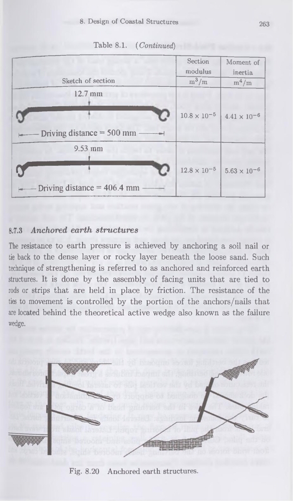
The résistance to earth pressure is achieved by anchoring a soil nail or
tie back to the dense layer or rocky layer beneath the loose sand. Such
technique of strengthening is referred to as anchored and reinforced earth
structures. It is done by the assembly of facing units that are tied to
rods or strips that are held in place by friction. The résistance of the
ties to movement is controlled by the portion of the anchors/nails that
are located behind the theoretical active wedge also known as the failure
wedge.
Fig. 8.20 Anchored earth structures.
263
Table 8.1. (Continuai)
Sketch of section
Section
modulus
Moment of
inertia
m3/m
m4/m
12.7 mm
H------ Driving distance = 500 mm--------- h
10.8 x 10“5 4.41 x 10“6
9.53 mm
(f
'"1""
.. .........
H----- Driving distance = 406.4 mm------12.8 X 10~5 5.63 X 10~6
8.7.3
Anchored earth structures
The résistance to earth pressure is achieved by anchoring a soil nail or
tie back to the dense layer or rocky layer beneath the loose sand. Such
technique of strengthening is referred to as anchored and reinforced earth
structures. It is done by the assembly of facing units that are tied to
rods or strips that are held in place by friction. The résistance of the
ties to movement is controlled by the portion of the anchors/nails that
are located behind the theoretical active wedge also known as the failure
wedge.
Fig. 8.20 Anchored earth structures.