

5. Rubble Mound Structures
165
Rubble mound or S-type breakwaters
Rubble mound breakwaters are frequently used structures. It consists of
armour layer, under layer, core and filter layer. It is a structure, built up
of core of quarry run rock overlain by one or two layers of large rocks. It
is easier to construct and damage normally occurs due to poor interlocking
capacity between individual blocks. Where large size natural rocks are not
available, artificial armour blocks are adopted, which will be discussed later.
Armour layer stability can be increased by using shape designed concrète
blocks, referred to as “artificial armour blocks” while, wave overtopping
can be reduced using a super-structure or crown wall over the top of the
mound (Type S with Superstructure). It is constructed by a heterogeneous
assemblage of natural rubble or undressed stone.
When water depths are large rubble mound breakwater may be uneconomical in view of huge volume of rocks required. It is unsuitable at locations when space is a constraint. These S-type of breakwaters dissipate
the incident wave energy by forcing them to break on a slope and thus
do not produce appréciable reflection. Energy lost due to friction, percolation through the porous medium and due to partial reflection. Due to
their armour, they are more durable and can be easily adapted to irregular
bathymetry. The stone and gravel accommodâtes settlement and thus being
flexible too. The gravel and sand cannot be laid on sand and hence requires
under layer if built on sand and also these are not suitable for soft ground.
The armour unit can be either quarry stones or concrète units dépends
on the availability. The placement of armour units can be both random or
regular arrangements which dépends on the type of armour units and the
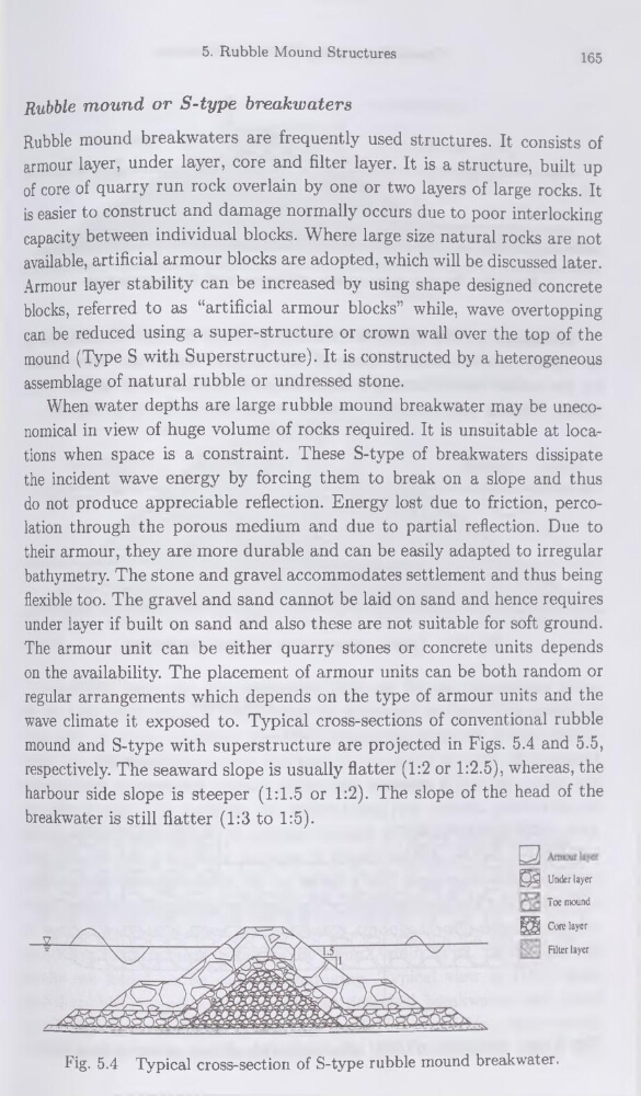
wave climate it exposed to. Typical cross-sections of conventional rubble
mound and S-type with superstructure are projected in Figs. 5.4 and 5.5,
respectively. The seaward slope is usually flatter (1:2 or 1:2.5), whereas, the
harbour side slope is steeper (1:1.5 or 1:2). The slope of the head of the
breakwater is still flatter (1:3 to 1:5).
Fig. 5.4 Typical cross-section of S-type rubble mound breakwater.
^5 Under layer
Toe mound
Ü Core layer
Filter layer
165
Rubble mound or S-type breakwaters
Rubble mound breakwaters are frequently used structures. It consists of
armour layer, under layer, core and filter layer. It is a structure, built up
of core of quarry run rock overlain by one or two layers of large rocks. It
is easier to construct and damage normally occurs due to poor interlocking
capacity between individual blocks. Where large size natural rocks are not
available, artificial armour blocks are adopted, which will be discussed later.
Armour layer stability can be increased by using shape designed concrète
blocks, referred to as “artificial armour blocks” while, wave overtopping
can be reduced using a super-structure or crown wall over the top of the
mound (Type S with Superstructure). It is constructed by a heterogeneous
assemblage of natural rubble or undressed stone.
When water depths are large rubble mound breakwater may be uneconomical in view of huge volume of rocks required. It is unsuitable at locations when space is a constraint. These S-type of breakwaters dissipate
the incident wave energy by forcing them to break on a slope and thus
do not produce appréciable reflection. Energy lost due to friction, percolation through the porous medium and due to partial reflection. Due to
their armour, they are more durable and can be easily adapted to irregular
bathymetry. The stone and gravel accommodâtes settlement and thus being
flexible too. The gravel and sand cannot be laid on sand and hence requires
under layer if built on sand and also these are not suitable for soft ground.
The armour unit can be either quarry stones or concrète units dépends
on the availability. The placement of armour units can be both random or
regular arrangements which dépends on the type of armour units and the
wave climate it exposed to. Typical cross-sections of conventional rubble
mound and S-type with superstructure are projected in Figs. 5.4 and 5.5,
respectively. The seaward slope is usually flatter (1:2 or 1:2.5), whereas, the
harbour side slope is steeper (1:1.5 or 1:2). The slope of the head of the
breakwater is still flatter (1:3 to 1:5).
Fig. 5.4 Typical cross-section of S-type rubble mound breakwater.
^5 Under layer
Toe mound
Ü Core layer
Filter layer