

Flow in porous media 177
and, the far upstream and downstream limits of the solution domain.
The nodes of the two-dimensional grid are characterized by an auxiliary matrix M(i,j) (the i index along the x-axis and the j index along
the y-axis). The values given to the elements of the matrix are M = 0
for the interior flow domain, M = 1 on impermeable boundaries and
M = any real number different than 1, signifying the magnitude of any
constant head boundary in metres. Other data used for this application are as follows:
Upstream piezometric head = 10 m
Downstream piezometric head = 2 m
Solution domain = 1500 m × 300 m
Discretization steps in x- and y-directions = 50 m and 10 m,
re spectively
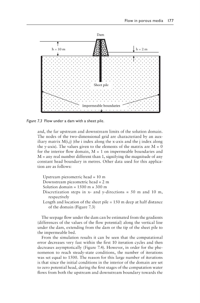
Length and location of the sheet pile = 150 m deep at half distance
of the domain (Figure 7.3)
The seepage flow under the dam can be estimated from the gradients
(differences of the values of the flow potential) along the vertical line
under the dam, extending from the dam or the tip of the sheet pile to
the impermeable bed.
From the simulation results it can be seen that the computational
error decreases very fast within the first 10 iteration cycles and then
decreases asymptotically (Figure 7.4). However, in order for the phenomenon to reach steady-state conditions, the number of iterations
was set equal to 1500. The reason for this large number of iterations
is that since the initial conditions in the interior of the domain are set
to zero potential head, during the first stages of the computation water
flows from both the upstream and downstream boundary towards the
Impermeable boundaries
h = 2 m
h = 10 m
Dam
Sheet pile
Figure 7.3 Flow under a dam with a sheet pile.
and, the far upstream and downstream limits of the solution domain.
The nodes of the two-dimensional grid are characterized by an auxiliary matrix M(i,j) (the i index along the x-axis and the j index along
the y-axis). The values given to the elements of the matrix are M = 0
for the interior flow domain, M = 1 on impermeable boundaries and
M = any real number different than 1, signifying the magnitude of any
constant head boundary in metres. Other data used for this application are as follows:
Upstream piezometric head = 10 m
Downstream piezometric head = 2 m
Solution domain = 1500 m × 300 m
Discretization steps in x- and y-directions = 50 m and 10 m,
re spectively
Length and location of the sheet pile = 150 m deep at half distance
of the domain (Figure 7.3)
The seepage flow under the dam can be estimated from the gradients
(differences of the values of the flow potential) along the vertical line
under the dam, extending from the dam or the tip of the sheet pile to
the impermeable bed.
From the simulation results it can be seen that the computational
error decreases very fast within the first 10 iteration cycles and then
decreases asymptotically (Figure 7.4). However, in order for the phenomenon to reach steady-state conditions, the number of iterations
was set equal to 1500. The reason for this large number of iterations
is that since the initial conditions in the interior of the domain are set
to zero potential head, during the first stages of the computation water
flows from both the upstream and downstream boundary towards the
Impermeable boundaries
h = 2 m
h = 10 m
Dam
Sheet pile
Figure 7.3 Flow under a dam with a sheet pile.