

20
STRUCTURB-ENVIRONMENTAL FORCE INTERACTIONS
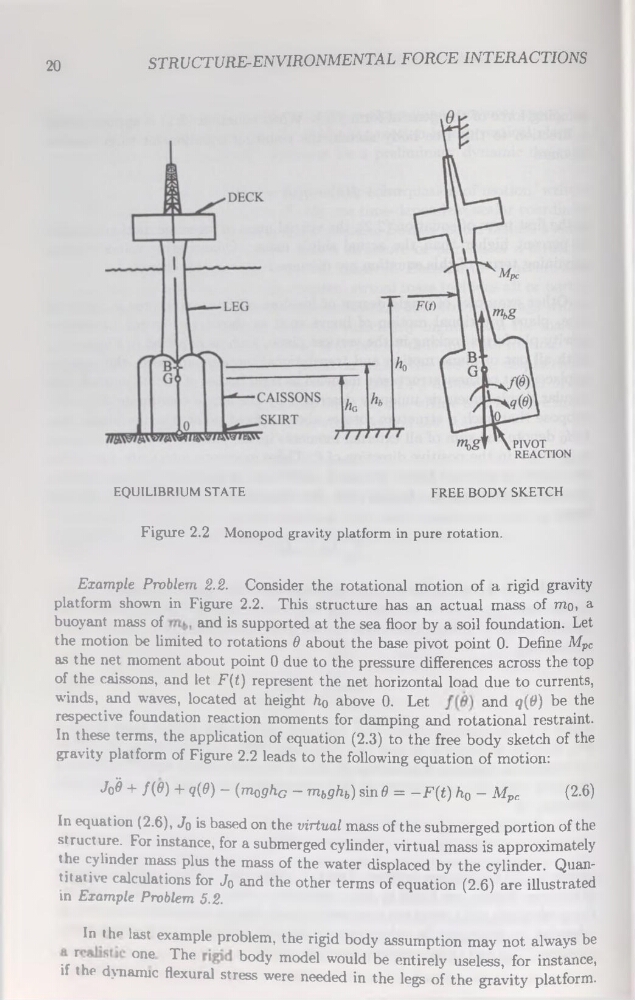
EQUILIBR1UM STATE
FREE BODY SKETCH
Figure 2.2 Monopod gravity platform in pure rotation.
Example Problem 2.2. Consider the rotational motion of a rigid gravity
platform shown in Figure 2.2. This structure has an actual mass of mo, a
buoyant mass of
and is supported at the sea floor by a soil foundation. Let
the motion be limited to rotations 6 about the base pivot point 0. Define Mpc
as the net moment about point 0 due to the pressure différences across the top
of the caissons, and let F(t) represent the net horizontal load due to currents,
winds, and waves, located at height h0 above 0. Let
and
In these terms, the application of équation (2.3) to the free body sketch of the
gravity platform of Figure 2.2 leads to the following équation of motion:
Jo'è + f(6) + q(d) - (moghG - mbghb) sin 6 = -F(£) h0 - Mpc
(2.6)
In équation (2.6), Jq is based on the Virtual mass of the submerged portion of the
structure. For instance, for a submerged cylinder, virtual mass is approximately
the cylinder mass plus the mass of the water displaced by the cylinder. Quantitative calculations for Jo and the other terms of équation (2.6) are illustrated
in Example Problem 5.2.
In thp last example problem, the rigid body assumption may not always be
t rk
°ne The
body model would be entirely useless, for instance,
if the dynanuc flexural stress were needed in the legs of the gravity platform.
STRUCTURB-ENVIRONMENTAL FORCE INTERACTIONS
EQUILIBR1UM STATE
FREE BODY SKETCH
Figure 2.2 Monopod gravity platform in pure rotation.
Example Problem 2.2. Consider the rotational motion of a rigid gravity
platform shown in Figure 2.2. This structure has an actual mass of mo, a
buoyant mass of
and is supported at the sea floor by a soil foundation. Let
the motion be limited to rotations 6 about the base pivot point 0. Define Mpc
as the net moment about point 0 due to the pressure différences across the top
of the caissons, and let F(t) represent the net horizontal load due to currents,
winds, and waves, located at height h0 above 0. Let
and
In these terms, the application of équation (2.3) to the free body sketch of the
gravity platform of Figure 2.2 leads to the following équation of motion:
Jo'è + f(6) + q(d) - (moghG - mbghb) sin 6 = -F(£) h0 - Mpc
(2.6)
In équation (2.6), Jq is based on the Virtual mass of the submerged portion of the
structure. For instance, for a submerged cylinder, virtual mass is approximately
the cylinder mass plus the mass of the water displaced by the cylinder. Quantitative calculations for Jo and the other terms of équation (2.6) are illustrated
in Example Problem 5.2.
In thp last example problem, the rigid body assumption may not always be
t rk
°ne The
body model would be entirely useless, for instance,
if the dynanuc flexural stress were needed in the legs of the gravity platform.