

AN EX AMPLE: LATERAL PILE LOADING
315
The bending moment along the length of a pile is of major concern for
an offshore structure and pile deflection in most cases is less important. Figure
11.18 shows these computed values of bending moments with the two procedures
for a latéral load of 60 kips. There is reasonable agreement in the results of
the two methods, with the computer results showing somewhat more bending
moment, perhaps because the use of the axial load of 500 kips. The position of
the jacket leg extension is indicated, which allows the moment at the top of the
30 in. section to be found. The maximum values of combined stress in the 30
in. section and the 33 in. section were computed, assuming that the jacket leg
extension was fully grouted so that the axial load at the mudline was taken by
both the 33 in. and the 30 in. sections; and it was found that the most critical
stress occurred at the top to the pile or where the pile joined the jacket.
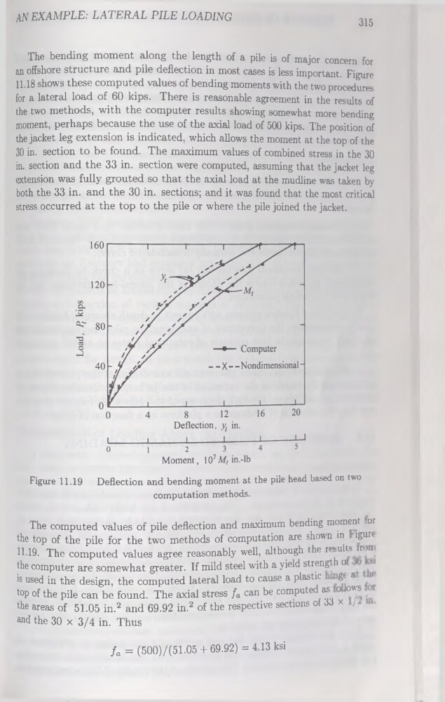
Deflection and bending moment at the pile head based on two
computation methods.
Figure 11.19
The computed values of pile deflection and maximum bending moment .or
the top of the pile for the two methods of computation are shown in igurt
11-19. The computed values agréé reasonably well, although the nsults îr>n.
the computer are somewhat greater. If mild steel with a yield strength o
-1
is used in the design, the computed latéral load to cause a plastic ge a
top of the pile can be found. The axial stress fa can be computed as o tows
the areas of 51.05 in.2 and 69.92 in.2 of the respective sections of 33 x /. i
and the 30 x 3/4 in. Thus
fa = (500)/(51.05 + 69.92) = 4.13 ksi
315
The bending moment along the length of a pile is of major concern for
an offshore structure and pile deflection in most cases is less important. Figure
11.18 shows these computed values of bending moments with the two procedures
for a latéral load of 60 kips. There is reasonable agreement in the results of
the two methods, with the computer results showing somewhat more bending
moment, perhaps because the use of the axial load of 500 kips. The position of
the jacket leg extension is indicated, which allows the moment at the top of the
30 in. section to be found. The maximum values of combined stress in the 30
in. section and the 33 in. section were computed, assuming that the jacket leg
extension was fully grouted so that the axial load at the mudline was taken by
both the 33 in. and the 30 in. sections; and it was found that the most critical
stress occurred at the top to the pile or where the pile joined the jacket.
Deflection and bending moment at the pile head based on two
computation methods.
Figure 11.19
The computed values of pile deflection and maximum bending moment .or
the top of the pile for the two methods of computation are shown in igurt
11-19. The computed values agréé reasonably well, although the nsults îr>n.
the computer are somewhat greater. If mild steel with a yield strength o
-1
is used in the design, the computed latéral load to cause a plastic ge a
top of the pile can be found. The axial stress fa can be computed as o tows
the areas of 51.05 in.2 and 69.92 in.2 of the respective sections of 33 x /. i
and the 30 x 3/4 in. Thus
fa = (500)/(51.05 + 69.92) = 4.13 ksi