

4
STRUCTURES IN THE OFFSHORE ENVIRONMENT
maximum depth is 1400 m. Sea floor pipelines are often anchored to the seabed
or buried in trenches for protection from érosion and the undermimng effects of
currents. Some seabed pipelines hâve a coating of concrète to add protection
and to reduce buoyancy.
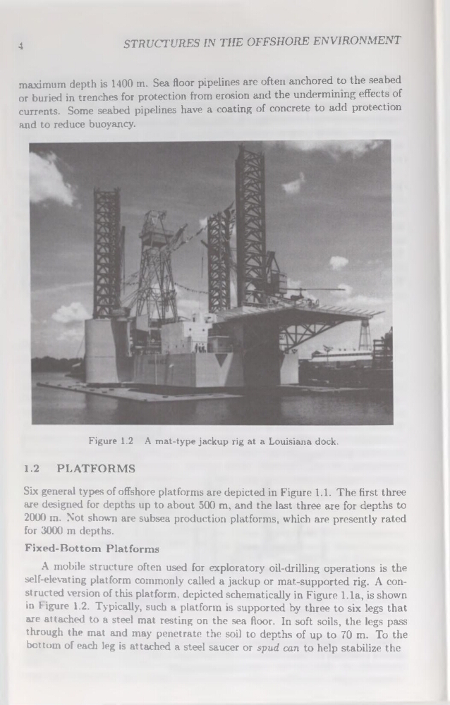
Figure 1.2 A mat-type jackup rig at a Louisiana dock.
1.2 PLATFORMS
Six general types of offshore platforms are depicted in Figure 1.1. The first three
are designed for depths up to about 500 m, and the last three are for depths to
2000 m. Not shown are subsea production platforms, which are presently rated
for 3000 m depths.
Fixed-Bottom Platforms
A mobile structure often used for exploratory oil-drilling operations is the
self-elevating platform commonly called a jackup or mat-supported rig. A constructed version of this platform, depicted schematically in Figure 1.1a, is shown
in I igure 1.2. Typically, such a platform is supported by three to six legs that
are attached to a Steel mat resting on the sea floor. In soft soils, the legs pass
through the mat and may penetrate the soil to depths of up to 70 m. To the
bottom of each leg is attached a Steel saucer or spud can to help stabilize the
STRUCTURES IN THE OFFSHORE ENVIRONMENT
maximum depth is 1400 m. Sea floor pipelines are often anchored to the seabed
or buried in trenches for protection from érosion and the undermimng effects of
currents. Some seabed pipelines hâve a coating of concrète to add protection
and to reduce buoyancy.
Figure 1.2 A mat-type jackup rig at a Louisiana dock.
1.2 PLATFORMS
Six general types of offshore platforms are depicted in Figure 1.1. The first three
are designed for depths up to about 500 m, and the last three are for depths to
2000 m. Not shown are subsea production platforms, which are presently rated
for 3000 m depths.
Fixed-Bottom Platforms
A mobile structure often used for exploratory oil-drilling operations is the
self-elevating platform commonly called a jackup or mat-supported rig. A constructed version of this platform, depicted schematically in Figure 1.1a, is shown
in I igure 1.2. Typically, such a platform is supported by three to six legs that
are attached to a Steel mat resting on the sea floor. In soft soils, the legs pass
through the mat and may penetrate the soil to depths of up to 70 m. To the
bottom of each leg is attached a Steel saucer or spud can to help stabilize the