

and suitably spaced orthogonals are drawn perpendicular to this wave front
and parallel to the chosen direction of wave approach. Closely spaced
orthogonals give more detailed results than widely spaced orthogonals.
These Unes are extended to the first depth contour shallower than L_/2
where Lo (in feet) = 5.12 T2.
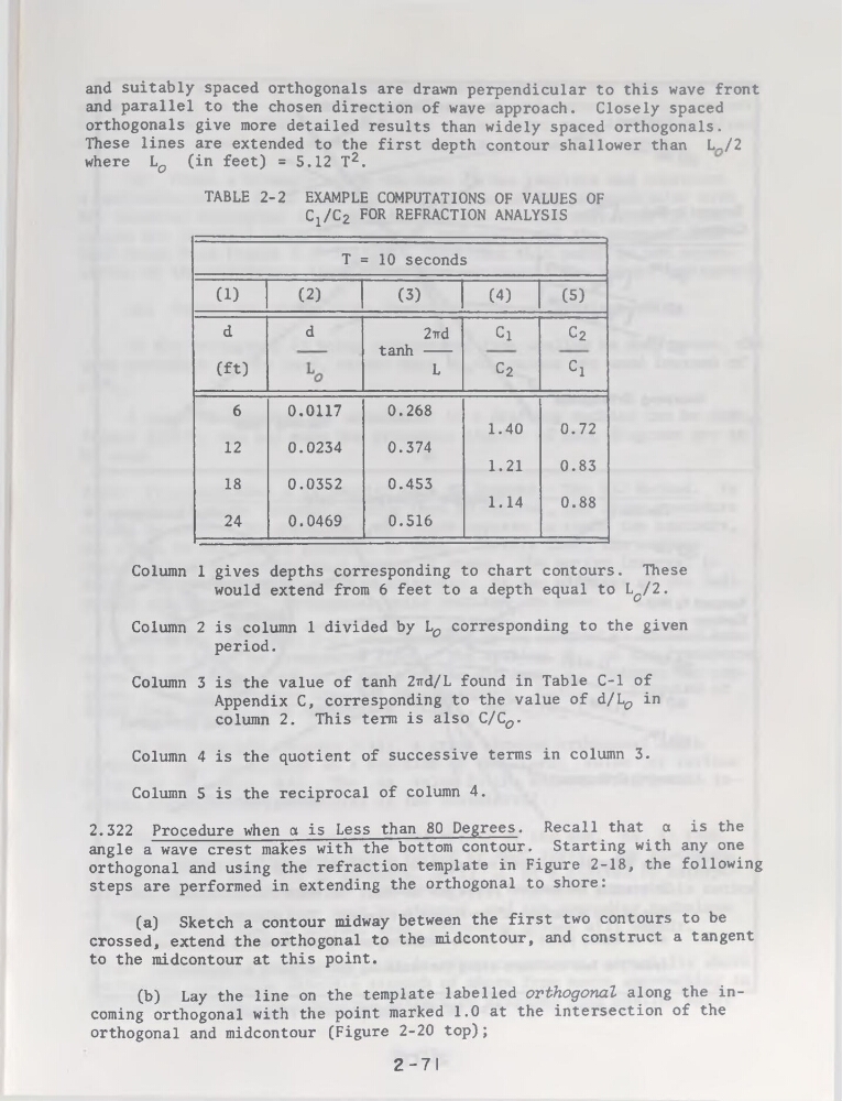
TABLE 2-2 EXAMPLE COMPUTATIONS OF VALUES OF
C1/C2 FOR REFRACTION ANALYSIS
T = 10 seconds
(D
(2)
(3)
(4)
(5)
d
d
2-iïd
tanh ----L
Cl
c2
(ft)
c2
Cl
6
0.0117
0.268
1.40
0.72
12
0.0234
0.374
1.21
0.83
18
0.0352
0.453
1.14
0.88
24
0.0469
0.516
Column 1 gives depths corresponding to chart contours. These
would extend from 6 feet to a depth equal to L^/2.
Column 2 is column 1 divided by Lo corresponding to the given
period.
Column 3 is the value of tanh 2ird/L found in Table C-l of
Appendix C, corresponding to the value of d/L^ in
column 2. This term is also C/Co.
Column 4 is the quotient of successive terms in column 3.
Column 5 is the reciprocal of column 4.
2.322 Procedure when a is Less than 80 Degrees. Recall that a is the
angle a wave crest makes with the bottom contour. Starting with any one
orthogonal and using the refraction template in Figure 2-18, the following
steps are performed in extending the orthogonal to shore:
(a) Sketch a contour midway between the first two contours to be
crossed, extend the orthogonal to the midcontour, and construct a tangent
to the midcontour at this point.
(b) Lay the line on the template labelled orthogonal along the incoming orthogonal with the point marked 1.0 at the intersection of the
orthogonal and midcontour (Figure 2-20 top);
2-71
and parallel to the chosen direction of wave approach. Closely spaced
orthogonals give more detailed results than widely spaced orthogonals.
These Unes are extended to the first depth contour shallower than L_/2
where Lo (in feet) = 5.12 T2.
TABLE 2-2 EXAMPLE COMPUTATIONS OF VALUES OF
C1/C2 FOR REFRACTION ANALYSIS
T = 10 seconds
(D
(2)
(3)
(4)
(5)
d
d
2-iïd
tanh ----L
Cl
c2
(ft)
c2
Cl
6
0.0117
0.268
1.40
0.72
12
0.0234
0.374
1.21
0.83
18
0.0352
0.453
1.14
0.88
24
0.0469
0.516
Column 1 gives depths corresponding to chart contours. These
would extend from 6 feet to a depth equal to L^/2.
Column 2 is column 1 divided by Lo corresponding to the given
period.
Column 3 is the value of tanh 2ird/L found in Table C-l of
Appendix C, corresponding to the value of d/L^ in
column 2. This term is also C/Co.
Column 4 is the quotient of successive terms in column 3.
Column 5 is the reciprocal of column 4.
2.322 Procedure when a is Less than 80 Degrees. Recall that a is the
angle a wave crest makes with the bottom contour. Starting with any one
orthogonal and using the refraction template in Figure 2-18, the following
steps are performed in extending the orthogonal to shore:
(a) Sketch a contour midway between the first two contours to be
crossed, extend the orthogonal to the midcontour, and construct a tangent
to the midcontour at this point.
(b) Lay the line on the template labelled orthogonal along the incoming orthogonal with the point marked 1.0 at the intersection of the
orthogonal and midcontour (Figure 2-20 top);
2-71