

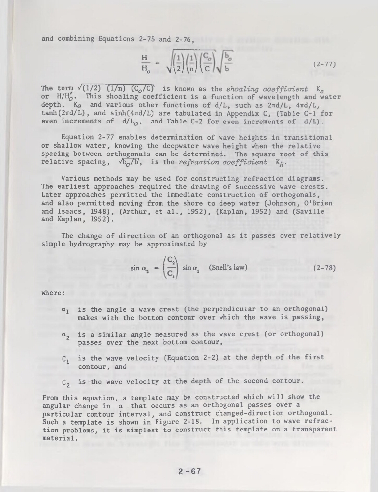
and combining Equations 2-75 and 2-76,
H =
Ho
N\2)\n)\C
b
(2-77)
The term /(1/2) (l/n) (Co/C)' is known as the shoaling coefficient Kg
or H/H^. This shoaling coefficient is a function of wavelength and water
depth. Kg and various other functions of d/L, such as 27rd/L, 4nd/L,
tanh(2ird/L) , and sinh(4nd/L) are tabulated in Appendix C, (Table C-l for
even incréments of d/L^, and Table C-2 for even incréments of d/L).
Equation 2-77 enables détermination of wave heights in transitional
or shallow water, knowing the deepwater wave height when the relative
spacing between orthogonals can be determined. The square root of this
relative spacing, /bo/b\ is the refraction coefficient K^.
Various methods may be used for constructing refraction diagrams.
The earliest approaches required the drawing of successive wave crests.
Later approaches permitted the immédiate construction of orthogonals,
and also permitted moving from the shore to deep water (Johnson, 0’Brien
and Isaacs, 1948), (Arthur, et al., 1952), (Kaplan, 1952) and (Saville
and Kaplan, 1952).
The change of direction of an orthogonal as it passes over relatively
simple hydrography may be approximated by
/C2\
sin a2 = I — sincq (Snell’s law)
(2-78)
where:
aj is the angle a wave crest (the perpendicular to an orthogonal)
makes with the bottom contour over which the wave is passing,
a2 is a similar angle measured as the wave crest (or orthogonal)
passes over the next bottom contour,
Cj is the wave velocity (Equation 2-2) at the depth of the first
contour, and
C2 is the wave velocity at the depth of the second contour.
From this équation, a template may be constructed which will show the
angular change in a that occurs as an orthogonal passes over a
particular contour interval, and construct changed-direction orthogonal.
Such a template is shown in Figure 2-18. In application to wave refraction problems, it is simplest to construct this template on a transparent
material.
2 -67
H =
Ho
N\2)\n)\C
b
(2-77)
The term /(1/2) (l/n) (Co/C)' is known as the shoaling coefficient Kg
or H/H^. This shoaling coefficient is a function of wavelength and water
depth. Kg and various other functions of d/L, such as 27rd/L, 4nd/L,
tanh(2ird/L) , and sinh(4nd/L) are tabulated in Appendix C, (Table C-l for
even incréments of d/L^, and Table C-2 for even incréments of d/L).
Equation 2-77 enables détermination of wave heights in transitional
or shallow water, knowing the deepwater wave height when the relative
spacing between orthogonals can be determined. The square root of this
relative spacing, /bo/b\ is the refraction coefficient K^.
Various methods may be used for constructing refraction diagrams.
The earliest approaches required the drawing of successive wave crests.
Later approaches permitted the immédiate construction of orthogonals,
and also permitted moving from the shore to deep water (Johnson, 0’Brien
and Isaacs, 1948), (Arthur, et al., 1952), (Kaplan, 1952) and (Saville
and Kaplan, 1952).
The change of direction of an orthogonal as it passes over relatively
simple hydrography may be approximated by
/C2\
sin a2 = I — sincq (Snell’s law)
(2-78)
where:
aj is the angle a wave crest (the perpendicular to an orthogonal)
makes with the bottom contour over which the wave is passing,
a2 is a similar angle measured as the wave crest (or orthogonal)
passes over the next bottom contour,
Cj is the wave velocity (Equation 2-2) at the depth of the first
contour, and
C2 is the wave velocity at the depth of the second contour.
From this équation, a template may be constructed which will show the
angular change in a that occurs as an orthogonal passes over a
particular contour interval, and construct changed-direction orthogonal.
Such a template is shown in Figure 2-18. In application to wave refraction problems, it is simplest to construct this template on a transparent
material.
2 -67