

360
M. V. L. BENNETT
ca re
1
1
2
3
1
2
3
1 2 3
i i i
1 2 3 r3’
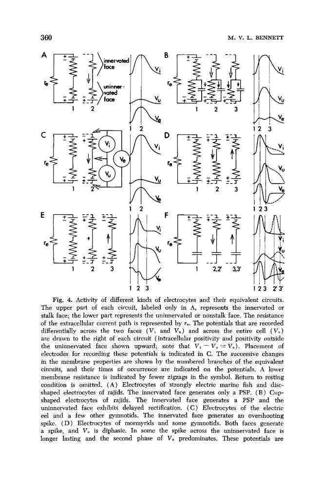
Fig. 4.. Activity of different kinds of electrocytes and their equivalent circuits.
The upper part of each circuit, labeled only in A, represents the innervated or
stalk face; the lower part represents the uninnervated or nonstalk face. The resistance
of the extracellular current path is represented by re. The potentials that are recorded
differentially across the two faces ( V , and V,) and across the entire cell (V,)
are drawn to the right of each circuit (intracellular positivity and positivity outside
the uninnervated face shown upward; note that Vi - V, = Ve). Placement of
electrodes for recording these potentials is indicated in C. The successive changes
in the membrane properties are shown by the numbered branches of the equivalent
circuits, and their times of occurrence are indicated on the potentials. A lower
membrane resistance is indicated by fewer zigzags in the symbol. Return to resting
condition is omitted. ( A ) Electrocytes of strongly electric marine fish and discshaped electrocytes of rajids. The innervated face generates only a PSP. ( B ) Cupshaped electrocytes of rajids. The innervated face generates a PSP and the
uninnervated face exhibits delayed rectification. ( C ) Electrocytes of the electric
eel and a few other gymnotids. The innervated face generates an overshooting
spike. ( D ) Electrocytes of mormyrids and some gymnotids. Both faces generate
a spike, and V, is diphasic. In some the spike across the uninnervated face is
longer lasting and the second phase of V, predominates. These potentials are
M. V. L. BENNETT
ca re
1
1
2
3
1
2
3
1 2 3
i i i
1 2 3 r3’
Fig. 4.. Activity of different kinds of electrocytes and their equivalent circuits.
The upper part of each circuit, labeled only in A, represents the innervated or
stalk face; the lower part represents the uninnervated or nonstalk face. The resistance
of the extracellular current path is represented by re. The potentials that are recorded
differentially across the two faces ( V , and V,) and across the entire cell (V,)
are drawn to the right of each circuit (intracellular positivity and positivity outside
the uninnervated face shown upward; note that Vi - V, = Ve). Placement of
electrodes for recording these potentials is indicated in C. The successive changes
in the membrane properties are shown by the numbered branches of the equivalent
circuits, and their times of occurrence are indicated on the potentials. A lower
membrane resistance is indicated by fewer zigzags in the symbol. Return to resting
condition is omitted. ( A ) Electrocytes of strongly electric marine fish and discshaped electrocytes of rajids. The innervated face generates only a PSP. ( B ) Cupshaped electrocytes of rajids. The innervated face generates a PSP and the
uninnervated face exhibits delayed rectification. ( C ) Electrocytes of the electric
eel and a few other gymnotids. The innervated face generates an overshooting
spike. ( D ) Electrocytes of mormyrids and some gymnotids. Both faces generate
a spike, and V, is diphasic. In some the spike across the uninnervated face is
longer lasting and the second phase of V, predominates. These potentials are